


10
ENGLISH
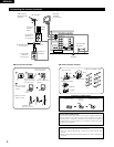
Protector circuit
•
This unit is equipped with a high-speed protection circuit. This circuit protects the internal circuitry from damage due to
large currents flowing if the speaker jacks are not completely connected or if an output is generated by a short circuit.
In such a case, the protection circuit will operate to cut off the output to the speakers. Should this happen, turn the
power off and check the speaker connections. Then turn the power on again. After muting for several seconds, the
receiver should be operating normally.
If the protection circuit is activated again even though there are no problems with the wiring or the ventilation around
the unit, switch off the power and contact a DENON service center.
Note on speaker impedance
•
The protector circuit may be activated if the set is played for long periods of time at high volumes when speakers with
an impedance lower than the specified impedance (for example speakers with an impedance of lower than 4 Ω/ohms)
are connected. If the protector circuit is activated, the speaker output is cut off. Turn off the set’s power, wait for the set
to cool down, improve the ventilation around the set, then turn the power back on.
6
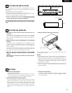
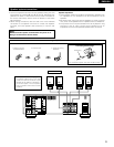
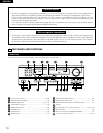
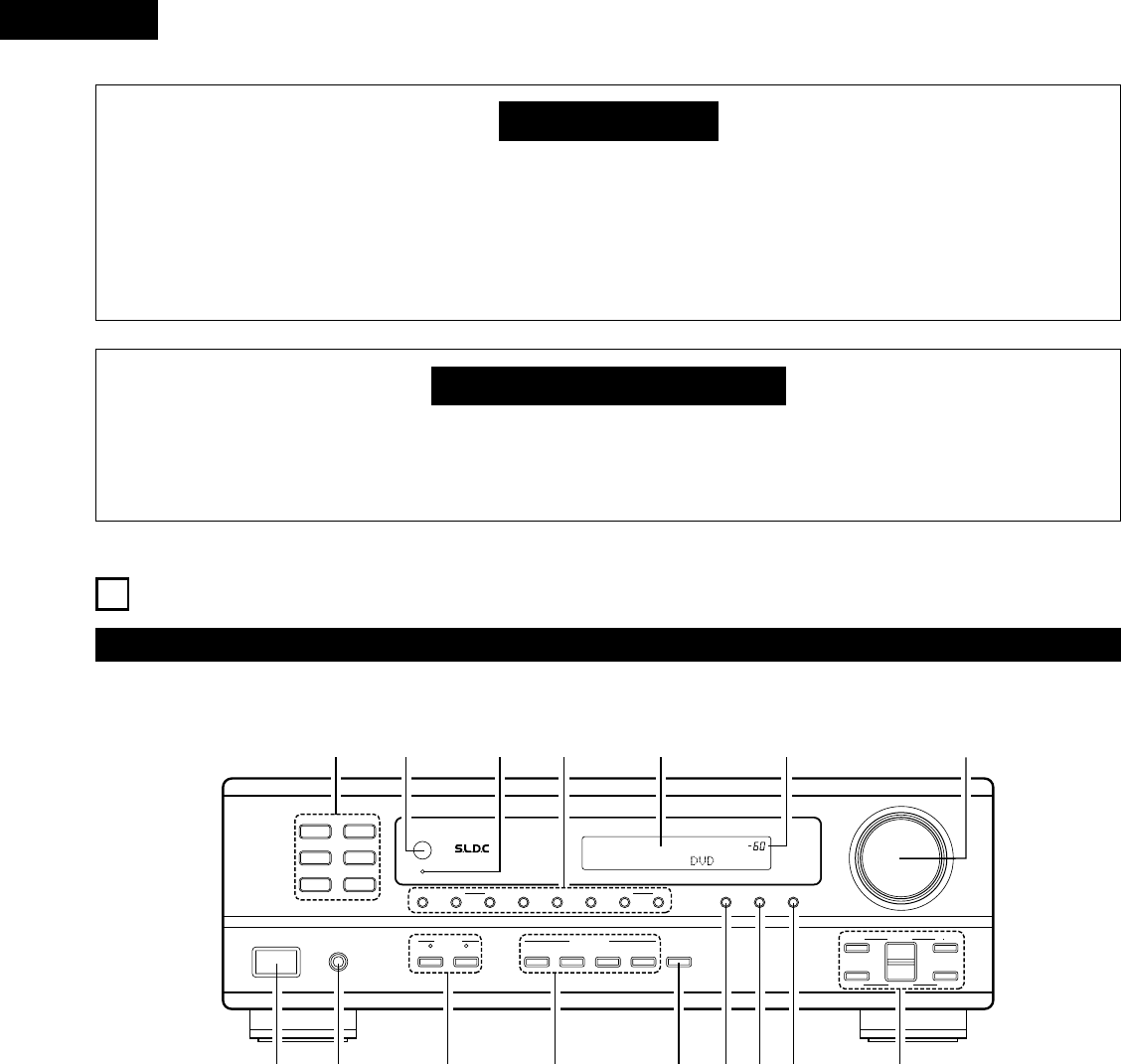
PART NAMES AND FUNCTIONS
Front Panel
• For details on the functions of these parts, refer to the pages given in parentheses ( ).
VOLUME LEVEL
B
DRA-295
PRECISION AUDIO COMPONENT / STEREO RECEIVER
PHONES
ON / STANDBY
SPEAKER
AB
TONE
CONTROL
TREBLEBASS
UP
TUNING
MODEBAND MEMORY
DIMMER
STATUS MUTING
SHIFT
DOWN UP
PRESET
DOWN
MASTER VOLUME
UP
DOWN
DVD / VDP
V.AUX
VCR
CD
TUNER
CDR / TAPE
ON / STANDBY
REMOTE
SENSOR
DVD / VDPSOURCE V. AUX VCR TONE DEFEAT
RIGHTLEFT BALANCE
VIDEO SELECT
q w re
!1
!2!3!5
!4
yot
!0!6
u i
q
Power operation switch ....................................................(12, 16)
w
Headphone jacks (PHONES) ...................................................(14)
e
SPEAKER A/B buttons ................................................(12, 14, 19)
r
VIDEO SELECT buttons ..........................................................(14)
t
TONE DEFEAT button.............................................................(13)
y
DIMMER button......................................................................(15)
u
STATUS button .......................................................................(15)
i
MUTING button.......................................................................(14)
o
TONE and BALANCE buttons .................................................(13)
!0
MASTER VOLUME control .....................................................(12)
!1
MASTER VOLUME indicator (VOLUME LEVEL).....................(12)
!2
Display
!3
Tuning/Preset memory selector buttons.....................(16, 17, 18)
!4
Power indicator .......................................................................(12)
!5
Remote control sensor (REMOTE SENSOR) ............................(5)
!6
Input source selector buttons ...........................................(12, 17)