8
ENGLISH
3
PART NAMES AND FUNCTIONS
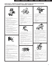
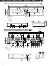
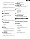
(1) DN-2100F Front Panel
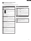
q
POWER button (¢ON £OFF)
• Press this button to turn the power on.
NOTE:
• Be sure to close the disc trays before turning off the power.
w
POWER indicator
• This red LED lights up when the power is on.
e
Disc tray
• Place CD discs in this tray.
• Press the disc tray OPEN/CLOSE button to open and close
the disc trays.
CAUTION:
• Do not place foreign objects in the disc trays. Doing so
could damage the player.
• Never push the disc tray in manually when the power is off.
This may result in malfunction or can damage the player.
r
Disc tray LED
• This yellow green LED flashes over the disc trays when
opening and closing.
• The LED also shines over the disc trays when opened, which
provideds sufficient illumination to see the extended disc tray
for easy loading.
t
Disc tray OPEN/CLOSE button
• Press this button to open and close the disc tray.
• To prevent accidental ejection, the disc trays will not open.
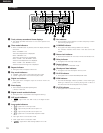
(2) DN-2100F Rear Panel
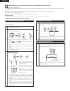
y
Analog output jacks 1, 2 (ANALOG OUT 1, 2)
• These are unbalanced RCA output jacks. The audio signals
from the CD players are connected to a mixer from these
jacks.
u
Digital output jacks 1, 2 (DIGITAL OUT 1, 2)
• Digital output data is available from these jacks only when
selected “ON” from the preset menu.
• We recommend using a 75Ω/ohm RCA cord for best digital
transfer. (available from any audio/video retailer)
NOTES:
• Turn PITCH control OFF when making digital recordings.
Most digital recorders will not accept a variable pitched
digital signal.
• The main functions are limited when digital out is selected.
(The loop, brake, Plat-H, Plat-S, Jog-Bend, scratch and key
adjust functions cannot be used.)
(3) RC-48 Front Panel
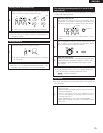
!0
Shuttle ring (outer ring)
• This control is used to select the scanning direction and
speed.
The CD is scanned in the forward direction when the shuttle
ring is turned clockwise from the center position. To scan
backwards, the shuttle ring is turned counterclockwise.
• The scanning speed increases as the wheel is turned further.
The shuttle ring is always active in any mode except “Digi-
Scratch” and “Plat-H”.
!1
Jog wheel (inner wheel)
• In the search mode, turn this dial during for search operation
to find the CUE point in units of frames.
• In the pitch bend and plat-H modes, turn this wheel to
change the playing speed.
• In the scratch mode, turn this wheel to scratch.
!2
FLIP button
• Press this button to switch between the loop mode/hot start
mode and stutter mode.
• The “ ” indicator lights when in the loop mode/hot start
mode.
!3
JOG MODE button
• This button is pressed to select the jog dial operating mode.
Manual search mode:
Turn the wheel clockwise to move the playback position
forward, counterwise to move the playback position
backward.
Pitch bend mode:
When the jog wheel is turned in either direction, the playback
speed changes within +/– 18% until released. (The green
LED Bend indicator lights up.)
Plat-H mode:
When the jog wheel is turned in either direction, the playback
speed changes within +40% –50% until released. (The green
LED Bend indicator flashes.).
(The BEND LED and the “ ” indicator light.)
PLAT-H
LOOP
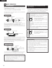
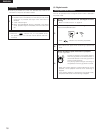
i
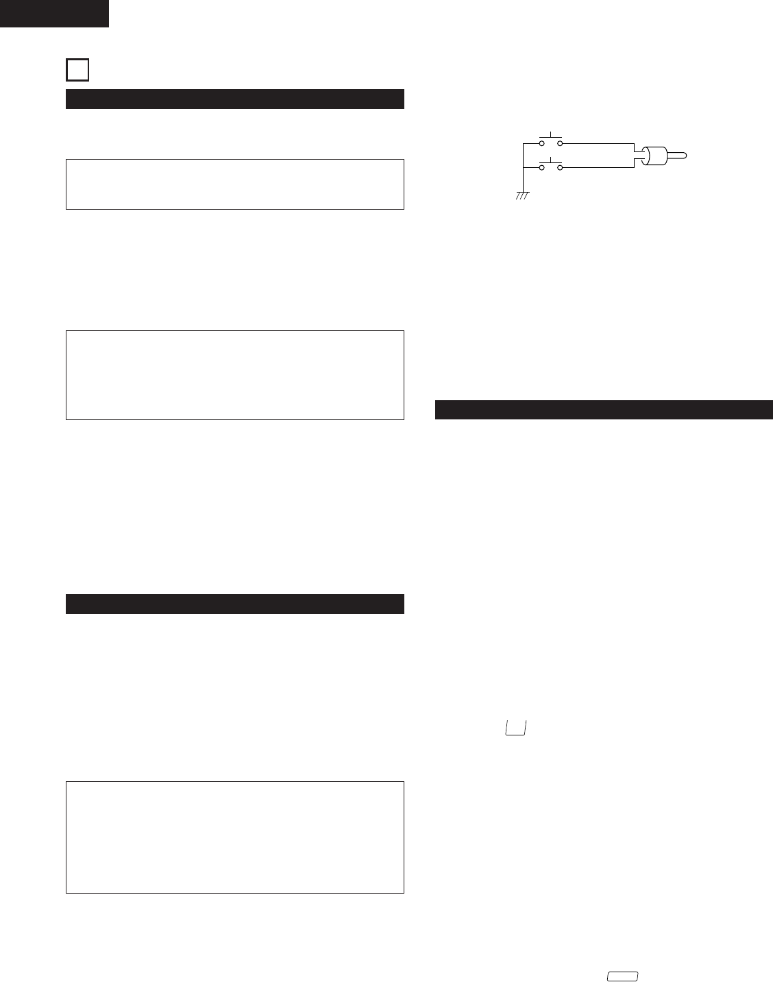
Fader Start input jacks 1, 2 (FADER 1, 2)
• To be connected with a compatible 5 volt pulse start mixer.
(3.5mm TRS mini jack)
(FADER INPUT LEVEL HCMOS (Ii=–3mA))
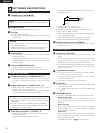
• The fader can be activated using the switch circuit shown on
the diagram below.
GND
*
SW 2
SW 1 TIP
SLEEVE
• Connect SW1 to the “TIP” terminal.
• Connect SW2 to the “SLEEVE” terminal.
• Connect GND* to the analog output “SLEEVE” terminal.
• Do not use the “RING” terminal.
• When SW1 is pressed, the hot start play mode selected with
the A1 and A2 buttons starts.
• When SW2 is pressed, the hot start play mode stops.
✽ Load the hot start data before starting fader playback.
o
Remote control connector (REMOTE)
• Connect this connector to the RC-48 control unit using the
included control cord.


