


ENGLISH
9
STAND-ALONE PLAYBACK
CONNECTION PRECAUTIONS
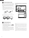
• Before proceeding with connections or disconnections of cable and
power cords, be sure to turn all system components off.
• Ensure that all cables are connected properly to the L (left) and R
(right) jacks.
• Insert plugs fully into the terminals.
• Connect the output jacks to the amplifier CD, AUX or TAPE PLAY
input jacks.
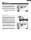
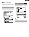
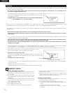
Connect one end of the connection cord supplied with the CD player to
the output terminals, left (L) and right (R) of the CD player, and the
other end to the CD, AUX, or TAPE PLAY input terminals, left (L) and
right (R), of the amplifier.
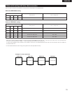
1234
1
DIGITAL COAX IN
DAISY CHAIN IN
REMOTE CONTROL IN
2
1
2
ANALOG OUT
RL
CONTROL
DAISY CHAIN
CONTROL
EXTERNAL
MODE SWITCH
¢ RS232C
£ RS422A
10
ATTENTION
ATTENTION
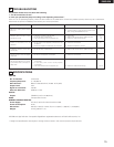
2
1
DIGITAL COAX OUT
DAISY CHAIN OUT
1
2
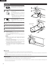
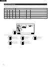
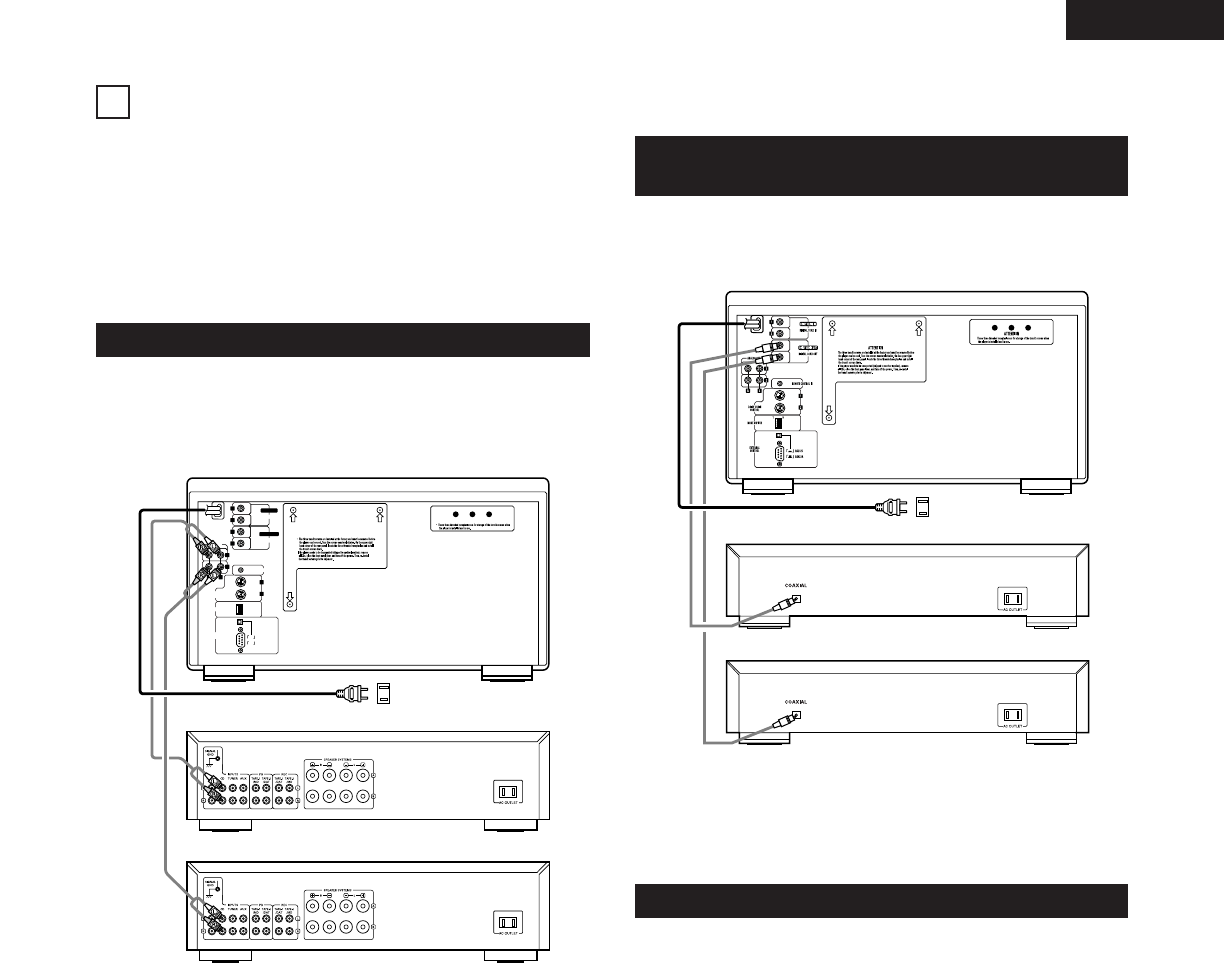
Use a 75 Ω/ohms coaxial pin cord to connect the digital output jack
(DIGITAL COAX OUT) of the DCM-5001 to the digital input jack
(COAXIAL) on a digital processor or D/A unit.
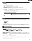
The DCM-5001 is provided with computer and remote control interface
ports, for compatibility with external remote control solutions offered
by third party vendors. Contact your dealer or installation consultant
for advice if you are considering the purchase of an external control
system.
NOTE:
When the single zone mode is selected, no digital data is output from
the ZONE 2 side.
6
Connecting the Analog Output Jacks
ZONE 2 Amplifier
ZONE 1 Amplifier
Power Supply outlet
Connecting the Digital Output Jack
(COAXIAL)
Other Connections
Power Supply outlet
ZONE 1 Digital processor or D/A converter unit (Amplifier)
ZONE 2 Digital processor or D/A converter unit (Amplifier)
DCM-5001
DCM-5001