Signal directionAudio cable
Connections
6
ENGLISH
ENGLISH
Cable indications
Connections
NOTE:
• Do not plug in the power supply cord until all connections have been completed.
• When making connections, also refer to the operating instructions of the other components.
• Be sure to connect the left and right channels properly (left with left, right with right).
• Making connections with the power turned on could result in noise or damage the speakers.
• Bunching the power supply cords and connection cables together could result in humming or noise.
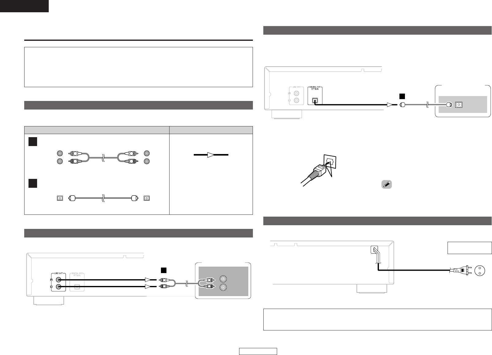
Connect using the connection cables shown below.
Analog connections (Stereo)
A
R
L
R
L
Pin-plug cable
Digital connections (Optical)
B
Optical fiber cable
Audio signal
OUT IN
(White)
(Red)
A
R
L
AUDIO IN
R
L
R
L
Analog connections
Stereo amplifier
B
OPTICAL
IN
Digital connections
CD recorder, etc.
There is a protective cap over the optical digital output terminal. Remove the protective cap and insert the
plug firmly until it locks.
¢ When connecting the optical digital output connector with an optical
transmission cable (commercially available)
Match the
shapes
Match the shapes then insert firmly all the way in.
• Store the protective cap in a safe place so as not
to lose it, and use it when not using the terminal.
Connecting the power supply cord
AC 230 V, 50 Hz
NOTE:
• Insert the plugs securely. Incomplete connections will result in the generation of noise.
• Do not unplug the power supply cord while the set is operating.
AC outlet
(wall)


