


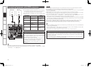
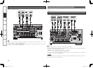
Multi-zone
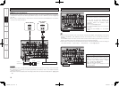
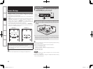
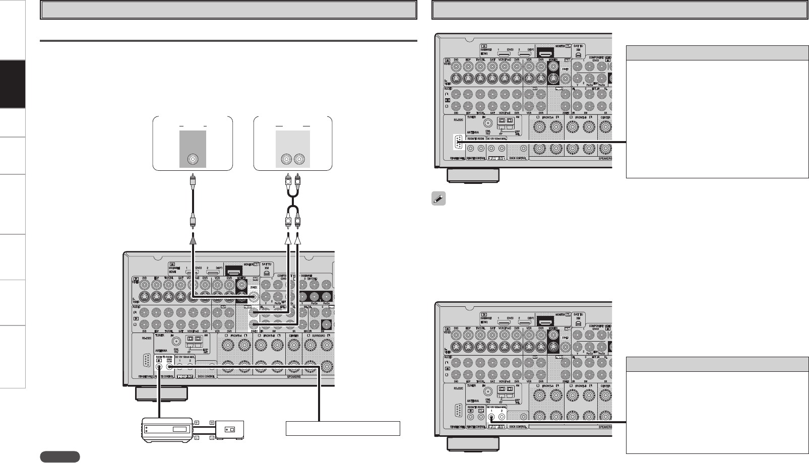
ZONE2 Pre-out Connections
• If another power amplifier or pre-main (integrated) amplifier is connected, the ZONE2 pre-out (variable or
fixed level) connectors can be used to play a different program source in ZONE2 the same time (vpage
55 ~ 58).
• When using an S-Video cable or a video cable for connection between the AVR-988 and an input device,
connect to the video connectors.
R
L
R
L
"6%*0
3-
*/*/
7*%&0
"6%*07*%&0
"69
065
Monitor (ZONE2)
Power amplier
(ZONE2)
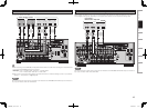
Input
Output
Infrared
retransmitter
Infrared
sensor
Extension jack for future use.
NOTE
• For the audio output, use high quality pin-plug cords so that no induction humming or noise is produced.
• For instructions on installing and operating separately sold devices, refer to the respective devices’
operating instructions.
• To conduct multi-zone playback, see “Amp Assign / Multi-zone Connections and Operations” (vpage 55
~ 58).
Getting Started Connections Setup Playback Remote Control Multi-Zone Information Troubleshooting
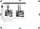
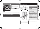
External Controller
• When using in combination with an RF Remote Controller (RC-7000CI, sold separately) or RF Remote
Receiver (RC-7001RCI, sold separately) two-way communication with an RF Remote Controller is
possible.
The AVR-988’s status information as well as iPod can be browsed watching the RF Remote Controller’s
display. For details, refer to the operating instructions of the respective devices.
• When used in combination with an RF Remote Controller or RF Remote Receiver, make the settings at
menu “Manual Setup” – “Option Setup” – “2Way Remote” – “Used” (vpage 32).
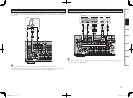
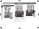
RS-232C connector
This connector is used for an external controller.
b If you wish to control the AVR-988 from
an external controller using the RS-232C
connector, perform the operation below
beforehand.
q Turn om the AVR-988’s power.
w Turn off the AVR-988’s power from the external
controller.
e Check that the AVR-988 is in the standby
mode.
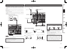
Trigger output jacks
The power of an external device equipped with
a trigger input jack can be turned on and off in
association with operations on the AVR-988. For
details, see menu “Manual Setup” – “Option
Setup” – “Trigger Out” (vpage 32).
• Output: DC 12 V 150 mA MAX.
Check the trigger input conditions of the
connected device.
1.AVR988EU_101_4th.indd 22 2007/09/13 11:31:47