


47*%&0
065
"6%*0 7*%&0
$0.10/&/57*%&0
: 1# 13
7*%&0
065065
"6%*0
3-
065 065
)%.*
065
$0"9*"-
R
L
R
L
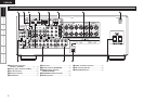
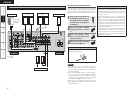
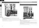
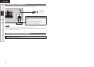
TV/CABLE Tuner
Connect the cables to be used.
TV tuner
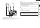
• When using a optical cable for the digital audio connection, make the settings at “System Setup” – “Input
Setup” – “Digital In Assign” (vpage 22).
• AVR-488’s S-Video connectors (input and output) and video connectors (input and output) have
independent circuit structures, so that video signals input from the S-Video connectors are only output
from the S-Video connector outputs and video signals input from the pin connectors are only output from
the pin connector outputs.
• The signals input to the component (color difference) video connectors are not output from the VIDEO
output connector (yellow) or the S-Video output connector.
Carefully check the left (L) and right (R) channels and the inputs and outputs, and be sure to interconnect
correctly.
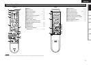
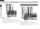
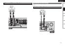
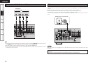
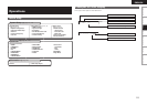
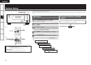
Connecting the Recording Components
Video Cassette Recorder
Connect the cables to be used.
47*%&0
065
3- 3-
065065*/
"6%*07*%&0
*/
"6%*07*%&0
*/
R
L
R
L
R
L
R
L
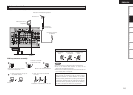
Video cassette recorder
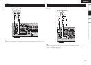
• When recording via the AVR-488, the playback device’s cable must be of the same type as the cable used
to connect the AVR-488’s VCR OUT connector.
Example: TV IN → S-Video cable : VCR OUT → S-Video cable
TV IN → Video cable : VCR OUT → Video cable
• AVR-488’s S-Video connectors (input and output) and video connectors (input and output) have
independent circuit structures, so that video signals input from the S-Video connectors are only output
from the S-Video connector outputs and video signals input from the pin connectors are only output from
the pin connector outputs.
• The signals input to the component (color difference) video connectors are not output from the VIDEO
output connector (yellow) or the S-Video output connector.
or
Connections
Getting Started Setup Playback Remote Control Information Troubleshooting
ENGLISH