


D.W. FEARN
VT-15 Recording Channel
22
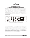
CONTROLS (see Figure 1.)
The VT-15 front panel is divided into three main areas of controls. On the left is the Input sec-
tion, to its right is the Compressor section, further right is the Equalizer section, and far right
is the output and power section.
Input Toggle Switch Section
The group of 6 toggle switches in the upper left sets up the VT-15 input configuration.
1. Mic/Line switch: In the Mic position, the XLR input connector on the rear panel accepts
mic level signals: nominally 150-ohm, balanced, at a -50dBm level. The Line position is for
+4dBm, balanced, 600-ohm signals.
2. 0/-20 switch: This is a 20dB pad that can be inserted on either the mic or line signal. In
the “0” position, microphone or line audio is connected directly to the input transformer.
This provides the proper amplification for most condenser microphones and line-level sig-
nals, and will be used in most situations. In the “0” position, the VT-15 can accept up to about
a -30 dBm input signal at 20 cps with full gain (53 dB) in the Mic position, and approximate-
ly +14dBm in the Line position, without an increase in distortion.
In the “-20” position, a pad is inserted between the input connector and the input trans-
former. This position would be used when the level is too high for the “0” position. On con-
denser microphones that have a switchable pad, it will usually be necessary to use a -10 or -
20 dB pad in the mic when recording very high sound levels to prevent overload of the micro-
phone electronics. Whether this is used in conjunction with or as a substitute for the VT-15
pad should be determined by experimentation. For the cleanest sound it is generally prefer-
able to pad at the microphone first, then at the VT-15 if necessary. The sound of some micro-
phones will change slightly from the “0” to “-20” position. This is a function of the interac-
tion between the microphone transformer and the VT-15 input transformer.
Sometimes a line-level signal will be too high for the VT-15 Line input. The -20 position can
be useful in this situation.
3.
150/Lo-z: Some microphones, particularly transformerless-output condenser mics, have
a non-standard output impedance, typically 50 to 80 ohms. (The AES standard is 150 ohms.)
The Lo-Z position often provides a better match to these microphones. The level is not
changed, but the microphone loading is improved for these low-impedance mics. Use your
ears to decide which position sounds best to you.
4.
+48 volt phantom power on/off switch: Supplies 48 volts for phantom powered con-
denser microphones. Switch the 48 volts off for dynamic and ribbon microphones, or con-
denser microphones with their own power supplies (e.g. vacuum tube condensers). This
function is locked-out when in the Line position. The phantom powering circuit used in the
VT-15 is suitable for use with all Neumann microphones, AKG 12 and 48 volt microphones,
B&K phantom powered mics, all Schoeps mics, Shure SM81 and 85 mics, Crown PZM mics,
and virtually all other phantom powered mics that require any voltage between 12 and 48.
When turned off, the phantom-power resistors are completely disconnected from the circuit
in the VT-15.
5.
Rev/Phase switch: Usually in the Normal position except when it is necessary to reverse the
polarity of a microphone or line signal. It does not function on the Inst input. This switch revers-