


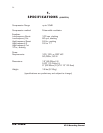

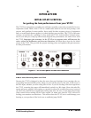

D.W. FEARN
VT-15 Recording Channel
17
3.
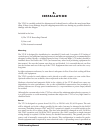
INSTALLATION
The VT-15 is carefully packed for shipment and it should survive all but the most brutal han-
dling. If there is any damage, keep the shipping material for use during any possible claim for
damage with the shipper.
Included in the box:
1) The VT-15 Recording Channel
2) Line cord
3) This instruction manual
Mounting
The VT-15 is designed for installation in a standard 19 inch rack. It requires 5.25 inches of
vertical space, but additional spacing between it and adjacent equipment is recommended for
adequate cooling. Ideally, a ventilated panel at least 1 rack unit high (1.75 inches) should be
installed above and below the VT-15 (and around any other heat producing equipment for
that matter). Be sure the bottom vent slots are not blocked. It is essential that air can flow
into the bottom and out of the top of the VT-15. Equipment that runs cool can last for a very
long time.
In tight equipment enclosures, be sure there is adequate air flow. Forced air cooling will ben-
efit all your equipment.
The VT-15 can also be used without a rack, placed on a table, counter, or even on the floor.
Optional rubber feet are available, when requested at the time of the order.
Moderate electrical and magnetic fields in the vicinity of the VT-15 should not cause any
degradation in noise performance, due to the well-shielded construction, but proximity to
devices with motors or large power transformers (i.e. tape machines or power amps) should
be avoided.
Although the vacuum tubes in the VT-15 are selected for minimum microphonic response, it
is a good practice to avoid mounting locations that subject the VT-15 to very high sound or
vibration levels.
Power
The VT-2 is designed to operate from 100, 120, or 220-240 volt, 50/60 Hz power. The unit
will be shipped set for the voltage specified in the order, but may be changed in the field if
necessary. Switching between 120V and 220V operation is simple: a recessed switch on the
rear panel can be set to either voltage. The fuse value should be changed as well: 2A SB for
100/120V operation, and 1A SB for 220V operation. (For 100V operation, a simple internal
wiring change is required. Call the factory for detailed instructions). The ground pin of the
power cord is internally connected to the chassis. This configuration is standard in profes-
sional equipment and is required by most electrical codes. A grounding screw is provided on