


D.W. FEARN
VT-15 Recording Channel
18
the back panel for installations that use separate chassis grounding. If ground loop hum is
detected, a careful check of the studio grounding scheme is needed. The VT-15 is less suscep-
tible to grounding problems than many studio devices.
Connections
The INPUT connector is a XLR-3 female wired with pin 1 ground, pin 2 “+” or “high,” and
pin 3 “-” or “low.” The same input is used for either mic input or line input. The input match-
es 150 ohm microphones or 600-ohm line signals and is transformer balanced.
The OUTPUT connectors are XLR-3 male wired with pin 1 ground, pin 2 “+” or “high,” and
pin 3 “-” or “low.” The VT-15 is optimized for feeding balanced bridging inputs. (Virtually all
modern audio equipment has bridging inputs.) The output is transformer-balanced.
The “GND” terminal is for use when an external grounding scheme is utilized.
The Fuse is a 3AG slow-blow type, 2 amp for 100 or 120 VAC operation, and 1 amp for 220-
240 volts.
The AC input connector is used with the mating line cord (supplied). For 120 VAC operation,
this cord is a Belden 17250 or equivalent.
The unit does not utilize any RFI filtering, and no RFI has been experienced, even when the
VT-15 is operated in close proximity to AM, FM, and TV broadcast transmitters.
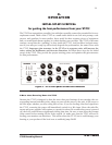
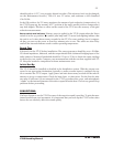
Input and Output Connections
See Figure 1. Gold-plated XLR connectors are used for inputs and outputs. The input connec-
tors are female and the outputs male.
All connectors are wired according to AES standard: pin 1 is ground (shield), pin 2 is “high”
or “+,” and pin 3 is “low” or “-.” A positive voltage on pin 2 of the input will result in a posi-
tive voltage on pin 2 of the output (with the Phase Reverse switch set to Normal).
Grounding and Shields
A full discussion of proper studio wiring schemes is beyond the scope of this manual, but, in
general, the Input mating XLR connector must have the cable shield connected to pin 1. With
most microphones, this shield must also be connected to pin 1 at the microphone end of the
cable.
Whether the shield is connected to pin 1 of the output connector depends on the standard
in your studio. The shield should be connected to ground at only one end of the output cable;
however, although not recommended, the shields can often be connected at both ends with-
out a problem.