


page 17
M Series Power Amplifiers
Operation Manual
The output transistors are protected by the Time
Dependent Voltage & Current circuit. This cir-
cuit protects the devices from extending
beyond their safe area of operation, but allows
the devices to provide high bursts of peak
power with music, allowing your amplifier to
deliver more punch. When all is said and done,
this amplifier output topology offers a good
combination of low quiescent amplifier heating,
great distortion performance at high powers,
and relative simplicity, with impressive reliabil-
ity and value.
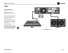
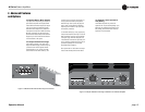
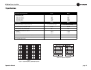
For extended flexibility, all of the amplifier’s
output power is delivered through the Channel
1 Neutrik
®
Speakon
®
connector. Both Channel
1 and 2 output terminals are wired through the
Channel 1 connector, allowing dual or bridge
mono applications to be available with one
speaker cable. Refer to Figure 2.3 and Table 1
for Neutrik
®
Speakon
®
output pin assign-
ments.
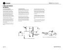
The output relay, in conjunction with input sig-
nal mute circuit, assures the amplifier will be
well-behaved during turn on and off. In the
event of an amplifier output failure, a triac will
activate to turn off the offending channel and
protect your speakers.
The turn on delay circuit functions to keep the
output relay open until all the voltages are up
and stable, both in the amplifier, and in all the
components in the system ahead of the ampli-
fier.
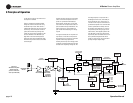
Heatsink temperature is monitored by a thermal
probe attached to the heatsink. As the tempera-
ture rises, the probe sends a proportional cur-
rent to the proportional speed fan circuit which
starts the fan. Should the power transformer
reach its maximum safe temperature, an inter-
nal thermal switch opens and the fan circuit
turns on full speed to quickly cool down the
amplifier. It also disconnects the load via the
output relay, removing any output current and
further speeding a cool-down cycle. Extra care
was taken during the design stage to set this
point both to protect your investment and to
guard against nuisance tripping.
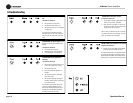
Whenever the heatsinks or the transformer
reach a maximum temperature, or during the
normal turn on delay window, the front panel
Fault LEDs will blink to get your attention.
A modular RJ-11 jack is mounted on the back
panel (similar to the type used on telephones).
Pins 2 and 5 are connected to an opto-isolator
which is always in a low-resistance state when-
ever the unit is on and happy. Should a fault be
detected or should the amplifier lose AC power,
the opto-isolator will change to a high resis-
tance, allowing the user
to remotely detect the status of the amplifier.
The Signal Presence Indicators tap the signal
chain just before the level controls and prior to
the power amplifier chain. They are not ampli-
fier output indicators and should only be used
to indicate the presence of signal to the ampli-
fier front end.
The Clip light is driven from the output of the
compressor circuitry and lights to indicate the
onset of audible distortion. The Power LED is
driven from the low-voltage supply.
A positive and negative regulator form the ±15-
volt power supplies. Add to that the main trans-
former, a full-wave bridge rectifier, and high
energy electrolytics to form the main power
supply. They are protected by the front-panel
line circuit breaker and controlled by the front-
panel power switch.
5 Principles of Operation