


page 13
M Series Power Amplifiers
Operation Manual
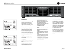
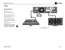
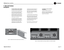
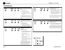
3.2 Front Panel Controls
and Indicators
A. Power Switch
Switch turns the amplifier on (“
| ”) or off
(“ 0 ”).
B. Reset Switch
This front-panel pushbutton is used to
reset the circuit breaker that protects the
power supply.
C. Power Indicator
Green LED indicates amplifier has been
turned on and AC power is available.
D. Signal, Clip and Fault Indicators
Signal: A green LED for each channel
flashes when a low-level signal (≥ 40 dBm)
is present at the input.
Clip: A red LED for each channel turns on
when distortion becomes audible in the
amplifier output.
Fault: Normally off, this red indicator will
blink under fault conditions. See Section
6, Troubleshooting.
E. Level Controls: Detented rotary level
control for each channel.
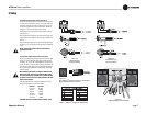
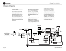
3.3 Back Panel Controls
and Connectors
F. Barrier Block Inputs: May be wired bal-
anced or unbalanced.
G. Neutrik
®
Combo Inputs: 1/4-inch
phone and XLR inputs. May be wired bal-
anced or unbalanced.
H. 5-way Binding Post Outputs: One pair
per channel; accept banana plugs, spade lugs
or bare wire. Note: Binding post outputs on
European models come with safety plugs
installed to prevent European power-cord plugs
from being inserted. The side entry positions
for these connectors should therefore be used
with European models.
I. IEC Power Connector
J. Fault Output: RJ11 jack allows monitoring
of the amplifier’s Fault status from a remote
location. See Section 4.2.
K. Stereo/Bridge-Mono Switch: Two-posi-
tion switch selects either Stereo or Bridge-
Mono operation.
L. Input Sensitivity Switch: Two-position
switch selects either 1.4 V sensitivity or 26 dB
gain.
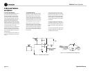
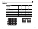
M. Neutrik
®
Speakon
®
Outputs: Two Neu-
trik Speakon NL3MP output connectors (mates
with NL4FC). See Figure 2.5 and Table 1 for
connector wiring.
3 Operation