


Operation Manual
M Series Power Amplifiers
page 14
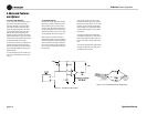
4.2 Fault Monitoring
The Fault (RJ-11) jack, which looks like a tele-
phone plug, is located on the back of your M-
Series amplifier. It gives you an easy way to
remotely monitor the amplifier’s fault status. To
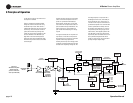
set up a circuit that will cause an LED to light
whenever a fault status occurs, you can simply
use the suggested circuit shown in Figure 4.1.
When using this circuit, the LED will glow
whenever the amplifier is in one of four states: a
channel’s heatsink has reached its temperature
limit, the transformer has reached its tempera-
ture limit, the amplifier has just been turned on
and is in its turn-on-delay mode, or the ampli-
fier is turned off.
If you choose to design your own circuit to
interface this signal to your system, note that
this RJ jack is polarity sensitive. Pin 2 must be
grounded, and Pin 5 must be supplied with a
positive voltage pull up (positive with respect
to ground). Refer to Figure 4.2 for RJ jack pin
assignments.
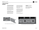
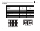
The mating connector for the M-Series RJ11
jack contains 4 contact pins in a 6-slot case, as
shown. For additional information please con-
tact your local dealer or Crown Technical Sup-
port.
The maximum signal that can be exposed to the
fault jack is 35 VDC and 10 mA. Best results
are obtained with 10 mA LEDs.
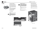
Figure 4.1 Fault Status LED Circuitry
Figure 4.2 RJ Jack Wiring and Pin Assignments
4.1 Crown SST Modules
Crown optional SST (System Solution Topolo-
gies) modules were specially designed to
improve the versatility of your audio system.
They feature a variety of professional signal
routing and filtering capabilities, with active
crossovers that allow the audio signal to be
split and sent to auxiliary amplifiers. Your
amplifier may have come with an SST module
already factory-installed, or your choice of SST
modules can be easily added to the amplifier by
any authorized Crown Service Center.
For information on wiring and configuration of
amplifiers equipped with an optional Crown
SST crossover module, please refer to the SST
Crossover Reference Manual included in your
literature package.
For more information and for newer SST mod-
ules, see the Crown website at www.crownau-
dio.com.
4 Advanced Features
and Options