


CE 4000
Power Amplifi er
Operation Manual
page 9
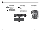
3 Setup
3.6 Wire Your System
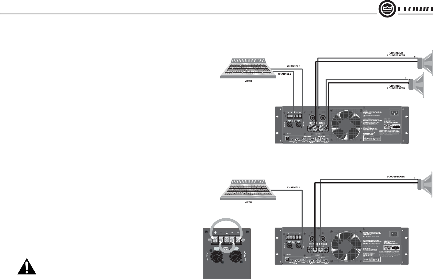
3.6.1 Stereo Mode
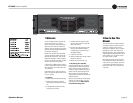
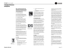
Typical input and output wiring is shown in Figure 3.8.
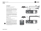
INPUTS: Connect input wiring for both channels.
OUTPUTS: Maintain proper polarity (+/-) on output connectors.
Connect Channel-1 positive (+) speaker load to Channel-1 positive terminal
of amp; repeat for negative (-). Repeat Channel-2 wiring as for Channel 1.
Refer to Section 3.6 for output connector pin assignments. Make sure the
Mode switch set to the “Stereo” position when operating in Stereo mode.
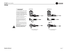
3.6.2 How to Parallel the Inputs
There are three ways to feed the same signal to each amplifi er channel:
1. Buy a “Y” cable. Plug the female end into your signal cable, and plug the
split male ends into both amplifi er inputs.
2. Feed your signal to the Channel-1 input (either barrier-block or combo).
Connect a jumper wire (Figure 3.9) between the barrier-block Channel-1
(+) screw terminal and the Channel-2 (+) screw terminal. Connect another
jumper wire between the Channel-1 (–) screw terminal and the Channel-2
(–) screw terminal.
3. Feed your signal to the Channel-1 input screw terminals. Using a mic
cable or phone-to-phone cable, connect Channel-1 combo jack to Channel-2
combo jack.
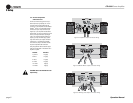
3.6.3 Bridge-Mono Mode
Typical input and output wiring is shown in Figure 3.10.
INPUTS: Connect input wiring to Channel 1.
OUTPUTS: Connect the speaker across the positive terminals of each chan-
nel. Do not use the negative terminals when the amp is being operated in
Bridge-Mono mode. Refer to Section 3.6 for output connector pin assign-
ments. Make sure the Mode switch is set to the “Bridge” position when
operating in Bridge-Mono mode.
NOTE: The Channel 2 level control should be set fully counter-
clockwise when operating the amplifi er in Bridge-Mono mode.
NOTE: Crown provides a reference of wiring pin assignments for commonly
used connector types in the Crown Amplifi er Application Guide (Section
1.21.) available at www.crownaudio.com
Figure 3.8 System Wiring, Stereo Mode
Figure 3.10 System Wiring, Bridge-Mono Mode
Figure 3.9
Jumper Placement to
Parallel the Inputs