


CE 4000
Power Amplifi er
Operation Manual
page 12
4 Operation
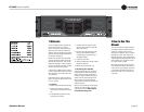
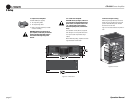
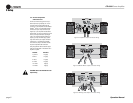
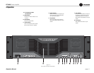
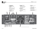
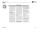
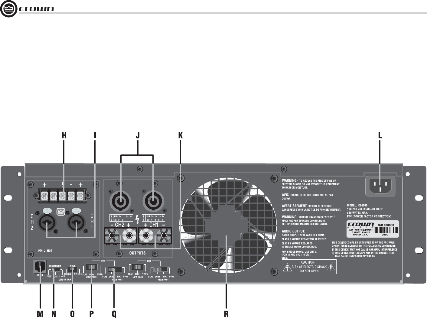
4.3 Back Panel Controls
and Connectors
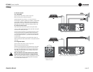
H. Balanced Barrier Block Inputs
(if equipped)
Screw-terminal Barrier Block. One set per
channel.
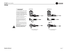
I. Neutrik
®
Combo Balanced Inputs
Combination three-pin female XLR and
TRS. One per channel.
J. Neutrik
®
Speakon
®
Outputs
(if equipped)
Accept male NL4C connector.
K. 5-Way Binding Post Outputs
(if equipped)
Accept banana plugs, spade lugs or bare
wire. (European models do not accept
banana plugs). One pair per channel
L. IEC Power Connector
M. Fault Connector
Female RJ-45 for connection to external
circuit to monitor amplifi er Fault status.
N. Sensitivity Switch
Allows selection of .775V, 1.4V or 26-dB
sensitivity.
O. Mode Switch
Allows selection of Stereo or Bridge
operation.
P. Low-Pass Filter Switch
Allows selection of Flat, 80 Hz or 100 Hz
roll-off. One per channel.
Q. High-Pass Filter Switch
Allows selection of Flat, 30 Hz, 40 Hz or 50
Hz roll-off. One per channel.
R. 3-Speed Fan-on-Demand
Provides forced-air cooling of the amplifi er.
Figure 4.2 Back Panel Controls and Connectors