


CE 4000
Power Amplifi er
Operation Manual
page 13
NOTE: For detailed information about
these Crown amplifi er features, please
consult the Crown Amplifi er Application
Guide, available on the Crown website
at www.crownaudio.com.
5.1 Protection Systems
Your Crown amplifi er provides extensive pro-
tection and diagnostic capabilities, including
built-in anti-clip limiters, amplifi er fault protec-
tion, and switchable high-pass fi lters.
5.1.1 Anti-Clip Limiters
Your Crown amplifi er has built-in Anti-Clip
Limiters which offer a degree of protection
to your loudspeakers. The Anti-Clip Limiters
work by dynamically reducing the amplifi er
gain if the output stage is driven into clip,
thereby reducing potentially damaging distor-
tion to moderate levels.
While some audio systems may already con-
tain protective limiters preceeding the amplifi er
in the system, the amplifi er’s Anti-Clip Limiters
generally will not noticeably affect output qual-
ity. For systems without additional protection,
the Anti-Clip Limiters can enhance your sys-
tem’s output quality and prevent catastrophic
damage to your speakers.
Even with the Anti-Clip Limiters, your amplifi er
should never be operated at a level which
causes the front-panel Clip LEDs to illuminate
constantly. While the Anti-Clip Limiters help to
prevent damage due to signal distortion, your
speakers can still be damaged by excess power
dissipation.
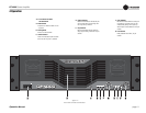
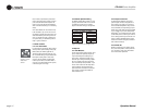
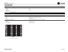
5.1.2 Fault
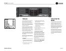
The amplifi er will light the Fault LED (Figure
5.1) of an amplifi er channel under fi ve different
conditions:
1. When the amplifi er is fi rst powered up,
until the unit is ready for operation.
2. If the heatsinks reach a temperature above
normal working limits.
3. If the transformer thermal protection cir-
cuit is activated.
5 Advanced Features
and Options
4. If amplifi er output wires develop a short-
circuit.
5. Should the amplifi er output stage become
non-operational.
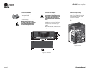
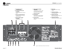
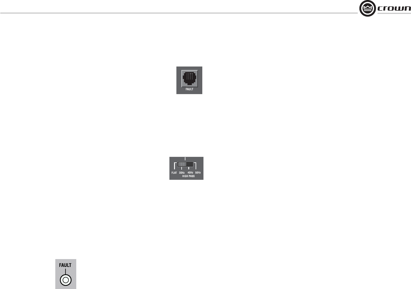
The Fault status of the amplifi er can also be
monitored remotely by attaching a signaling
device to the Fault jack (see Figure 5.2). For
suggestions for external signaling circuits to
use, see Section 1.5 of the Crown Amplifi er
Application Guide, available on the Crown
website at www.crownaudio.com.
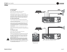
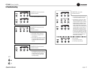
5.1.3 High-Pass Filters
Very low frequency signals contain no useful
musical energy, waste valuable amplifi er power
and headroom, and can be damaging to
your speakers. Your Crown amplifi er provides
switchable high-pass fi lters to remove these
signals from each channel’s output.
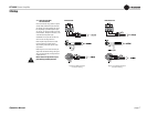
For each channel, a back-panel, three-position
switch provides optional settings of Flat, 30
Hz, 40 Hz, or 50 Hz (left to right, see Figure
5.3). The 30 Hz setting is suitable for all
full-range and low-frequency applications. The
lower-frequency settings may be selected when
the amplifi er is being used to drive a sub-bass
program; use only with speakers that provide a
useful frequency response below the frequency
setting. The FLAT setting provides bypass of
the high-pass fi lters, for use when subsonic
protection is provided elsewhere in the system.
5.2 Circuit Designs
5.2.1 BCA
BCA (Balanced Current Amplifi er) is Crown’s
patented, cutting-edge technology that gets
more power out of an amplifi er with less waste
than was ever before possible. A completely
new adaptation of standard amplifi er design,
Crown’s BCA “switching” amplifi er design pro-
vides for high output, exceptional reliability
and nearly twice the effi ciency of typical ampli-
fi er designs.
Crown’s BCA “switching” technology is a com-
pletely new adaptation of standard switching
(PWM) amplifi er design. In fact, BCA is differ-
ent enough from other amplifi er classes that
it received a patent and merits it’s own class
designation, “class-I.”
BCA technology offers several key advantages.
It provides unprecedented effi ciency, requiring
less power from the AC supply than other
designs, meaning signifi cant cost savings over
the life of the amplifi er. BCA handles reactive
speaker loads easily and gracefully, by reusing
energy returned from the speaker rather than
dissipating it as heat or forcing the amp into
premature current-limiting. This ability makes
BCA models extremely resilient—especially at
low, 2-ohm impedances. It also makes them
more reliable, since they are not constantly
stressed to their limits or subjected to exces-
sive heat. Best of all, as proud owners can
attest, amps with BCA technology sound great,
with a powerful low-end that stands out from
the competition.
5.2.2 Switching Power Supply with
PFC
Crown’s new Switching Power Supply with PFC
provides a range of benefi ts over both non-
switching and conventional switching power-
supply designs.
Typical non-switching power supplies require
large, heavy transformers in order to produce
the required power at the output stage. These
transformers must be large to absorb the sub-
stantial waste that occurs when operating at 50
to 60 Hz (standard AC supplied by the power
company).
By contrast, switching power supplies can
operate with a much smaller (and lighter)
transformer because they fi rst convert the AC
up to a much higher frequency, thereby reduc-
ing waste.
However, in both non-switching and conven-
tional switching designs, phase differences
occur within the power supply due to the
inductance of the transformer. This phase dif-
ference prevents much of the available power
from the AC mains from making its way to the
load.
Figure 5.3 High-
Pass Filter Switch
Figure 5.1
Fault Indicator
Figure 5.2
Fault Jack