Commercial Audio Series Business Music System
page 11
Operation Manual
2.5 Wire Your System
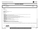
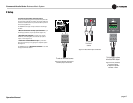
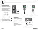
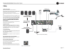
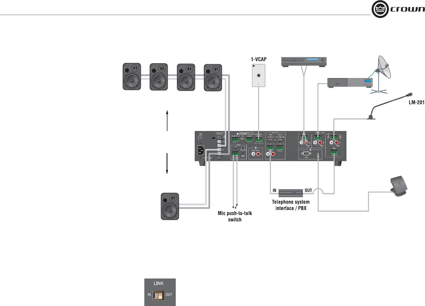
Typical input and output wiring is shown in Figure 2.11.
INPUTS: Connect microphones or balanced line-level sources to mixer-
amplifier balanced inputs. Set Mic/Line switches accordingly. Connect
unbalanced line-level signals to RCA input connectors.
OUTPUTS: Maintain proper polarity (+/–) on amplifier output connec-
tors.
Connect the Amplifier Output screw terminals to loudspeakers. Use ter-
minals marked COM and 25V or 70V for constant-voltage loudspeaker
loads, such as the JBL Control 1ST speaker included with the 180MAx
Pack. Use terminals marked 4-ohms for one 4-ohm speaker or two 8-
ohm speakers in parallel. Connect 70V speakers or 4-8 ohm
speakers to the 180MAx, but not both, as this would over-
drive the amplifier.
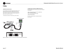
Connect the COM terminal to speaker negative (–) lead; connect one of
the other terminals to speaker positive (+) lead.
2.6 Phantom Power
Condenser mics require phantom power to operate. If you are using a
condenser microphone with the 180MAx on Input 1, turn on the Phan-
tom Power Switch on the back of the mixer-amplifier. The microphone
must be able to work on 15V phantom power, which the 180MAx mic
input connector provides.
2.7 Link In/Out Switch
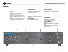
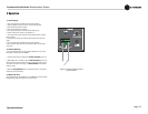
This switch (Figure 2.11) affects which signals are heard when another
mixer is wired to the mixer-amplifier.
IN: Any signal applied to the AMP INPUT connector will be mixed with
the input signal(s).
OUT: Only the signal from the AMP INPUT connector will appear at the
amplifier output.
How to link another mixer to your mixer-amplifier:
Connect the extra mixer’s LINE OUT connector to the mixer-amplifier’s
AMP INPUT connector. Set the Link switch to IN.
How to set up Music-On-Hold output:
Connect mixer-amp LINE OUT to Music-On-Hold input on telephone
system interface/PBX. Set the LINK SWITCH to IN.
How to set up a processing loop:
Connect mixer-amp LINE OUT to processor input. Connect processor
output to mixer-amp AMP INPUT connector. Set the Link switch to OUT.
2 Setup
CONNECT 70V SPEAKERS
OR 4-8 OHMS SPEAKERS,
BUT NOT BOTH.
70V speakers
(four JBL Control 1ST speakers
supplied only with 180MAx Pack)
One 4-ohm speaker
or two 8-ohm speakers in parallel
XM antenna
Satellite receiver
CD/DVD player
Figure 2.10 Input and Output Wiring
Figure 2.11 Link In/Out Switch


