


WR 3M Page 17 of 21
ENFRITESPTNLSVDKFIGRTRCZPLHUSKSLEELVLT
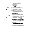
WARNING!
Vacuum pump will be destroyed if operated without
the filter.
Z Check to ensure the filters are in place before operating unit.
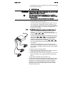
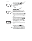
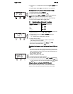
Replacing the filter
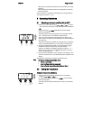
1. Turn the cover cap for "Vac“ (14) or "Air“ (15) 45°
counterclockwise and remove.
2. Pull out the contaminated filter and dispose of properly.
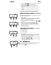
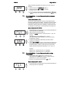
3. Insert an original WELLER filter cartridge.
Make sure that the cover seal is correctly seated.
4. Insert pressure spring.
5. Align the cover cap with slight pressure and turn 45° clockwise.
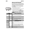
9 Fault Indications and Correction
Indication/symptom Possible cause Corrective Action
Display: "- - -"
− Tool has not been detected
− Tool defective
− Check connection of tool to
device
− Check connected tool
HAP 200 does not function HAP 200 not connected to
channel 1
Connect HAP 200 to channel 1
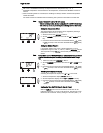
Display: "tip" Soldering tip of WMRP
Microtool or WMRT Micro-
Tweezer not correctly inserted
or defective
− Insert soldering tip or Tweezer
Cartridge again
− Replace defective soldering tip
or Tweezer Cartridge
Pick-up does not function
correctly
− Vacuum is not fully built up
− Hose defective or kinked
− Check vacuum at pick-up
connection
− Replace/straighten hose
No air at HAP Air hose not or incorrectly
connected
Connect air hose to AIR port
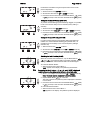
No vacuum on Desoldering
tool
− Vacuum hose not or
incorrectly connected
− Desoldering Tiplet clogged
− Desoldering Filter clogged
− Connect vacuum hose to Vac
port
− Clean Desoldering Tiplet with
cleaning tool
− Replace Desoldering Tool
Filter
Status indication of Vac
LED’s incorrect
Vacuum level not correctly set Set vacuum level in special menu
2
No display function (display
off)
No power supply voltage
− Turn on power switch
− Check power supply voltage
− Check device fuse
VAC LED red Vacuum system clogged
− Clean suction nozzle or
replace Desoldering Tiplet
− Check filter (13); replace if
clogged