


Removal and Replacement Procedures
Maintenance and Service Guide 5–3
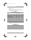
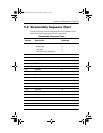
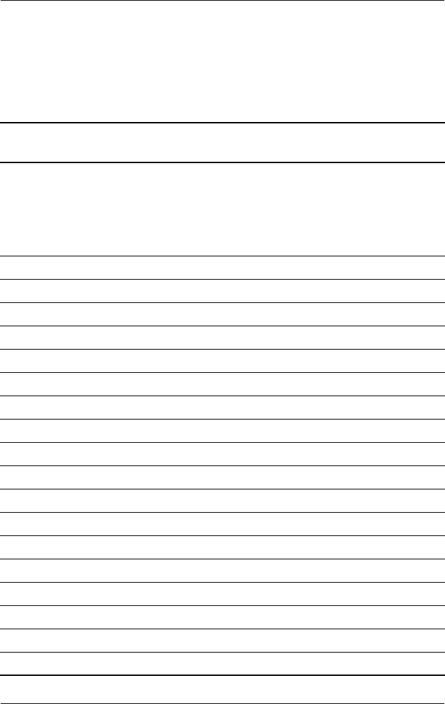
5.2 Disassembly Sequence Chart
Use the following chart to determine the section number to be
referenced when removing notebook components.
Disassembly Sequence Chart
Section Description
# of Screws
Removed
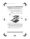
5.3 Preparing the notebook for disassembly
Battery pack 0
Hard drive 2
Hard drive cover and shield 4
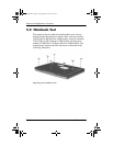
5.4 Notebook feet 0
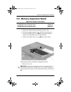
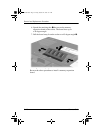
5.5 Memory expansion board 1
5.6 Mini PCI communications board 1
5.7 RTC battery 0
5.8 Optical drive 1
5.9 Keyboard 2
5.10 Switch cover 0
5.11 Speaker cover 4
5.12 Fan 1
5.13 Heat sink 4
5.14 Processor 0
5.15 Display assembly 7
5.16 Top cover 16
5.17 Bluetooth board 2
5.18 SD Card slot board and cable 2
5.19 VGA board and shield 2
5.20 Modem board and cable 0
5.21 System board 1
325388-002.book Page 3 Friday, October 24, 2003 9:21 AM