


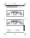
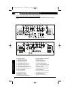
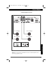
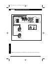
CONNECTIONS
APX640.4/640.2/320.2/DPX1001.1
8
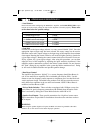
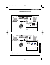
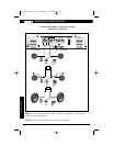
• Load Selector
Please note that when configuring the DPX1001.1 amplifier, the LOAD SELECTOR switch
must be set in the correct position in order for the amplifier to function properly.
Please refer
to the chart below for specific settings.
SUBWOOFER IMPEDANCE LOAD SELECTOR SWITCH SETTING
2-OHM Bridged Load 1 OHM
4~8-OHM Bridged Load 2-4 OHM
1-OHM Load on each output 1 OHM
2-OHM Load on each output 2-4 OHM
4 OHM Load on each output 2-4 OHM
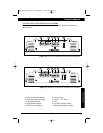
• Gain Dial
Located next to the input voltage selector, is a rotary control labeled "Gain". Once the
appropriate input voltage range has been selected, this rotary control can be used to
match the source unit's output voltage to the input stage of the amplifier for maximum
clean output. Rotating the control clockwise will result in higher sensitivity (louder for
a given input voltage). Rotating the control counter-clockwise will result in lower sen-
sitivity (quieter for a given input voltage). After using this procedure, you can then
adjust the level of the amplifier by adjusting the input sensitivity downward, if the
amplifier requires attenuation to achieve the desired system balance. Do not increase
the "Gain" setting for any amplifier in the system beyond the maximum level. Doing
so will result in audible distortion and possible speaker damage.
• Bass Boost Control
The amplifier also features a “high-Q” (i.e., narrow frequency band) Bass Boost cir-
cuit. It acts much like an equalizer with a switchable gain fixed at 45Hz. Use this
feature to tune low-frequency audio response to compensate for a less than ideal sub-
woofer enclosure design. The added boost produces rich, full bass tones that are nor-
mally difficult to reproduce in the car audio environment. NOTE: If Bass Boost is
undesired, set Bass Boost to OFF.
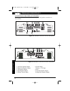
• X-Over Mode Switches - These switches are equipped with 12dB per octave elec-
tronic filters for precise frequency attenuation with minimal phase distortion. Each
filter is activated by sliding the X-Over Mode Switch to either HP or LP.
• Speaker Level Inputs - These provide connections for a high-level stereo source.
These connections are provided for installations when the source unit does not have
RCA outputs.
WARNING:
When using the speaker (high-level) inputs, the Black wire must be grounded at the radio.
Failure to do so will result in noise and/or improper operation.
apx-dpx-update.qxp 8/18/2004 8:46 AM Page 8