


Owner’s Manual
7
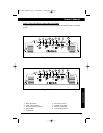
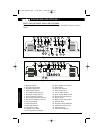
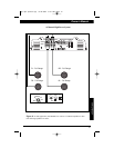
CONNECTIONS
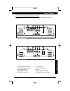
The Input Connections are gold-plated RCA Jacks. The Gain Controls provide a
wide adjustment range to accommodate output levels from any source unit brand.
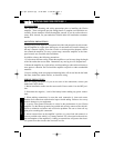
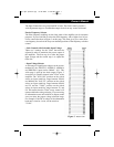
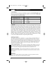
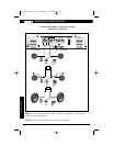
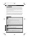
Precise Frequency Selector
The filter frequency markings on the front panel of the amplifier are for reference
purposes. If you would like to select the filter frequency with a higher level of pre-
cision, consult the chart in Figure 3 on this page. This chart gives you a more accu-
rate frequency for each of the forty-one detented positions of the frequency selection
control.
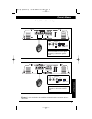
• Gain Controls with Selectable Input Voltage
There are 2 settings for the "Gain" that must be
adjusted in order to maximize the power output of
the amplifier. The first step is to select the proper
input voltage and the second step is to adjust the
Gain dial.
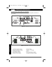
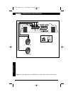
• Input Voltage Selector
A wide range of signal input voltages can be accom-
modated by the APX320.2, APX640.2, APX640.4
and DPX1001.1 input section (200mV - 8V). This
wide range is split up into three ranges, Figure 2,
accessible via switches located in the "Gain" of the
amplifier. The "0.2V-0.6V" position on the switch
selects an input sensitivity range between 200mV
and 600mV, the "0.6V-2V" position on the switch
selects an input sensitivity range between 600mV
and 2V and the "2V-8V" position on the switch
selects an input sensitivity range between 2V and
8V. This means that the "Gain" rotary control will
operate within that voltage window. If you are using
an aftermarket source unit with RCA outputs, make
sure you select the proper voltage selection range.
For example, if the RCA voltage of the aftermarket
head unit is rated at 4 volts, set the switch at
"2V-8V".
Figure 3 - Detent Chart
apx-dpx-update.qxp 8/18/2004 8:46 AM Page 7