


APX640.4/640.2/320.2/DPX1001.1
6
INPUT
FRONT
FREQ
RANGE
X10
X1
0.2V-0.6V
0.6V-4V
2V-8V
0.2V-0.6V
0.6V-4V
2V-8V
FRONT
HIGH
Level
L
R
L
R
+
-
+
-
(2 CH. IN)
REAR
FRONT
GAIN
REAR
GAIN
BASS
BOOST
FREQ Hz
dB
15
0
110
240
330
550
55
HP
LP
OFF
SOURCE
SELECT
2 CH.2 CH.
BASS
2 CH.
4 CH.
FREQ Hz
110
240
330
550
55
STEREO
BRIDGED (F R IN)
L & R SUM MONO
REAR
STEREO
BRIDGED (R L IN)
L & R MONO
HP
LP
OFF
HIGH
Level
L
R
+
-
+
-
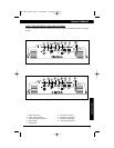
APX640.4
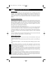
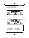
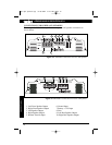
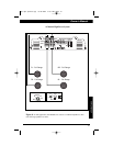
INPUT CONNECTIONS AND AUDIO CONTROL
Clarion amplifiers contain connections for RCA Inputs and Audio Control as shown
below.
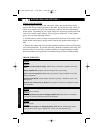
1. RCA Input Jacks
2. Front RCA Input Jacks
3. Rear RCA Input Jacks
4. Input Voltage Selector
5. Front Input Voltage Selector
6. Rear Input Voltage Selector
7. Precise Frequency Selector
8. Front Precise Frequency Selector
9. Rear Precise Frequency Selector
12. Front Input Mode
13. Rear Input Mode
14. Rear Input Selector
15. Bass Boost Control
16. Speaker Lever Inputs
17. Front Speaker Level Inputs
18. Rear Speaker Level Inputs
19. Gain Control
20. Front Gain Control
21. Rear Gain Control
22. X-Over Mode Switch
23. Front X-Over Mode Switch
24. Rear X-Over Mode Switch
25. X-Over Slope
26. Remote Level Control Port
27. Subsonic Filter
28. Frequency Range Multiplier
29. Impedance Load Selector
30. Input Sensitivity
31. Bass Boost Frequency
Figure 2-1 APX640.4 Input Connections and Audio Control
24
BASS
BOOST
0
15
dB
55
110
550
330
240
24 dB
12dB
+
-
-
L
R
SPEAKER
LEVEL IN
GAIN
L
R
INPUT
XOVER
FREQ Hz
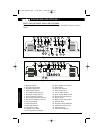
DPX1001.1
XOVER
SLOPE
MIN
MAX
2-4 OHM
1 OHM
INPUT
2V-8V
REMOTE
LEVEL
+
SUBSONIC
FILTER
OFF
ON
.6V-2V
.2V-.6V
SENSITIVITY
30
125
BASS
BOOST
FREQ Hz
LOAD
USA
GND
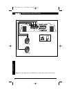
Figure 2-2 DPX1001.1 Input Connections and Audio Control
15
3
9
2
5
14
6
28
8
12
13
17
18
23
20
21
1
16
19
15
22
25
29
26
27
CONNECTIONS
30
31
apx-dpx-update.qxp 8/18/2004 8:46 AM Page 6