


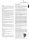
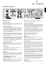
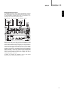
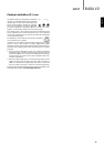
R
L
R
L
Input 1
(Unbalanced)
Input 1 Balanced Audio
GND
5
840A V2azur
ENGLISH
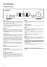
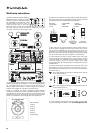
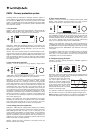
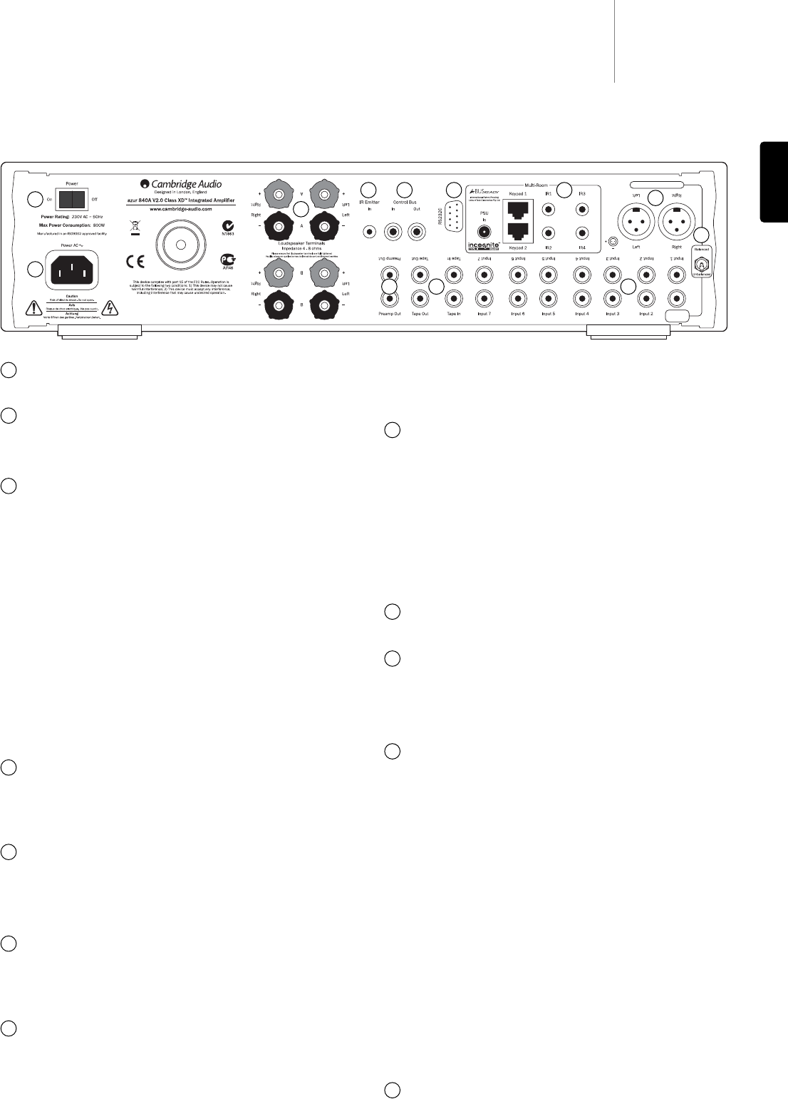
Rear panel connections
Power On/Off
Switches the unit on and off.
AC power socket
Once you have completed all connections to the amplifier, plug the AC
power cable into an appropriate mains socket then switch on. Your
amplifier is now ready for use.
Loudspeaker terminals
Two sets of loudspeaker terminals are available, A (main loudspeaker
terminals) and B (secondary loudspeaker terminals). Both sets of
speakers can be turned on and off independently. Connect the wires
from your left channel loudspeaker to the LEFT + & - terminals, and
the wires from the right channel loudspeaker to the RIGHT + & -
terminals. In each case, the red terminal is the positive output and the
black terminal is the negative output.
Care should be taken to ensure no stray strands of wire short the
speaker outputs together. Please ensure that the loudspeaker terminals
have been tightened completely to provide a good electrical
connection. It is possible for the sound quality to be affected if the
screw terminals are loose.
Note: When using one pair of speakers, use speakers with a nominal
impedance of between 4-8 ohms. When using two pairs of speakers,
use speakers with a nominal impedance of between 6-8 ohms. Please
also note that when multiple speakers are connected across the
amplifier’s outputs, the load (as seen by the amplifier) is reduced. This
will make the amplifier work harder, and hotter!
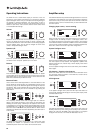
IR (Infrared) Emitter In
Allows modulated IR commands from multi-room systems to be
received by the amplifier. Commands received here are not looped out
of the Control Bus. Refer to the ‘Custom installation’ section for more
information.
Control Bus
In - Allows un-modulated commands from multi-rooms systems or
other components to be received by the unit.
Out - Loop out for control bus commands to another unit. Also allows
the 840A V2 to control some Cambridge Audio units.
RS232C
The RS232C port allows external serial control of the 840A V2 for
custom install use. A full command set is available on the Cambridge
Audio website at www.cambridge-audio.com. This port can also be
used by Cambridge Audio service personnel for software updates.
A-BUS™ Ready / Incognito Ready™
multi-room outputs
PSU - Connect an Incognito PS5 to supply power to the connected
multi-room keypads/speakers.
Keypad 1/2 - Connect one or two Incognito A-BUS KP10 keypads (or
other A-BUS compatible keypads) using CAT-5/5e cable. Incognito
AS10 Active Ceiling Speakers can also be connected here.
IR - Four IR outputs for remote control of source equipment.
Please refer to the ‘Multi-Room’ section of this manual for more
information on connections and set-ups.
Input 1 Balanced Audio
Input 1 features either unbalanced (phono/RCA) or balanced (XLR)
connections. Either type may be used but not both at the same time.
The balanced connection is the higher quality option and can reject
noise and interference in the cable when used with other equipment
that supports this function. An XLR connector is wired Pin 1 - Ground;
Pin 2 - Hot (in-phase); Pin 3 - Cold (phase-inverted).
Use the Balanced/Unbalanced switch (Item 9) to select the connection
type you wish to use. When using either the balanced or unbalanced
input, make sure that no cables or equipment are connected to the
unused input, as this may degrade operation. The unused input does
not require to be terminated and this should not be done.
Input 1 Balanced/Unbalanced switch
Use to select the connection type for Input 1.
Inputs 1-7
These inputs are suitable for any 'line level' source equipment such as
CD players, DAB or FM/AM tuners etc.
Note: These inputs are for analog audio signals only. They should not be
connected to the digital output of a CD player or any other digital device.
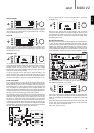
Tape/Rec In/Out
Connect to a tape deck or to the analog output sockets on a MiniDisc,
portable digital music player or CD recorder using an interconnect cable
from the recorder's Line Out sockets to the amplifier's Tape In sockets.
The Tape Input circuit of the 840A V2 is a "monitor" type, different from
the other 7 inputs. For the 7 normal inputs, the source selected for
listening to will be sent out of the Tape Out for recording. The source
currently being listened to and (optionally) recorded is then shown on
the front panel display.
However, when the Tape Input is selected a solid circle will appear
beside TAPE MON indicating that the Tape Input is now being listened
to with a different source being sent out of the Tape Out for recording.
The recording source is also shown by a solid circle by the selected
input and can be changed by pressing the other source buttons.
To switch Tape Monitor off, simply press the Tape Mon input select
button again, toggling this function off.
This feature is most useful when using 3-head analog cassette decks
which allow the signal being recorded to be played back live off tape
(via a 3rd head) whilst it is simultaneously recorded. It is then possible
by toggling the Tape Monitor input on and off to compare directly in real
time the original and recorded signal so that adjustments to the
recording parameters of the tape machine can be made (consult the
manual of your 3-head analog cassette deck for full details).
Preamp Out
Connect these sockets to the inputs on an external power amplifier(s)
or active subwoofers etc.
1
1
2
3
4 65
8
101112
2
3
7
5
6
8
9
11
4
10
9
7
12