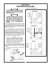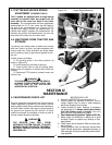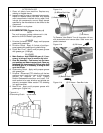
STANDARD CROP DIVIDER (Figure 4-6) Reattach
the cap and cutter to the crop divider by reinstalling
the four(4) capscrews through the top of crop divider
and tightening securely.
OPTIONAL CROP DIVIDER (Figure 4-7) Tilt cap
sideways and insert cap assembly into the top of the
crop divider. Insert pointed end of threaded rod into
the center hole on the end of the round output shaft.
Tighten cap by turning threaded rod clockwise so cap
moves up on threaded rod until it fits tight into taper
of crop divider. Tighten jam nut. Snap on hub cap.
4-7 CUTTER BAR REMOVAL
A. Lower cutter bar to rest on the ground.
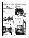
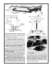
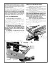
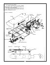
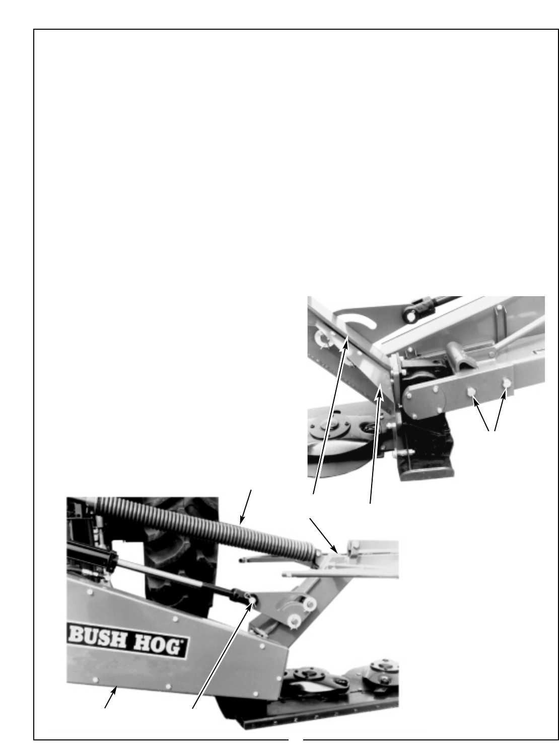
B. Remove pin (Figure 4-9) and disconnect cylin-
der from cylinder lug. For models with cutter bar
helper spring only, disconnect helper spring assem-
bly from curtain/beam assembly.
C. Detach shield and curtain/beam assembly
from the gearbox/cutter bar assembly. (Figure 4-9)
D. Remove belt shield rear cover. (Figure 4-9)
E. Loosen tension then remove the belts.
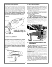
F. Remove three bolts securing sheave to gear-
box input shaft. Install bolts in adjacent holes and
progressively tighten to remove sheave from tapered
hub. (Figure 4-11
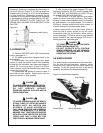
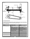
G. Remove the two bolts securing the front
mounting lug (Figure 4-10). Remove front mounting
lug. Detach gearbox/cutter bar assembly from the
main beam/hitch frame assembly.
4-8 CUTTER BAR INSTALLATION
A. Install gearbox into frame, securing with front
mounting lug and two bolts. (Figure 4-10)
B. Install sheave (Figure 4-11) onto gearbox input
shaft and key aligning with driver sheave. Alternately
tighten the three retaining bolts.
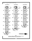
C. Install matched set of belts (Figure 4-11) Tighten
adjusting nut until belts deflect 1/2” with 10 pounds of
force applied. Rotate belt pulleys 6 complete revolu-
tions to seat the belts into the pulleys. Tighten
adjusting nut a second time until the belts deflect 1/2 “
with 10 pounds of force applied. Tighten jam nut on
adjusting nut and tighten assembly pivot bolt.
D. Install belt shield rear cover. Figure 4-9)
E. Attach shield and curtain/beam assembly to
gearbox/cutter bar assembly. (Figure 4-9)
F. Pin cylinder to cylinder lug. For models with cut-
ter bar helper spring assembly, attach spring assembly
to curtain/beam assembly. (Figure 4-9)
Belt Shield Cylinder Pin
Figure 4-9 Helper Spring
Figure 4-10
16
Curtain/Beam
Assembly
Two Bolts Securing
Front Mounting Lug
Shield


