


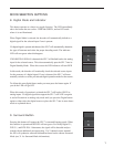
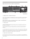
7. Remote 12V Trigger Outputs
Two trigger outputs are provided. The output labeled “ON/OFF” provides a 12V voltage level whenever the unit
is fully powered up. When the unit goes into standby, the level is 0 Volts.
The output labeled “AUX” is programmable from the LCD menu as described below. This means that the termi-
nal supplies the 12-Volt signal only when you switch to certain, specified inputs.
The Centre (Common or Ground) terminal is always used with the “ON/OFF” or “AUX” terminals to complete
the circuit loop. The 12-Volt connector will accept 1/4 - inch stripped wire ends, inserted into the square holes
provided, and the adjacent screws carefully tightened to hold them in place.
These can be used to control any Bryston Power amplifier and many other components such as motorized
screens and drapes. Be sure to determine what type of trigger signal the selected components requires and what
function will be enabled by the trigger signal’s voltage.
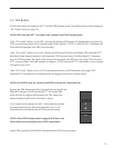
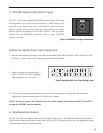
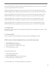
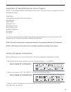
Programming the AUX Trigger Output
i. Enter the main menu by pressing on one of the menu buttons on the SP1 front panel. Move the cursor to
“OS”. Hit ‘Select’ - You are now in the Other Settings (Optical/THX) Menu.
ii. Move the cursor to “T”. (T = Trigger) Hit ‘Select’. Now you can assign the AUX Trigger output to ON or
OFF, for each of the 6 input sources.
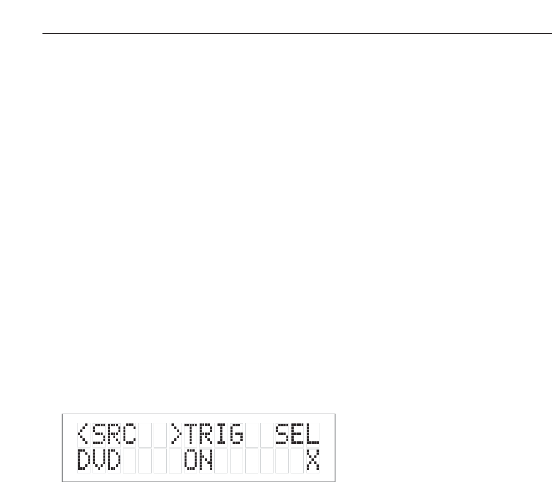
iii. To change the source, use the “<” button. To toggle the trigger setting On or Off, use the “>” button.
Hit ‘Select’ to exit when finished.
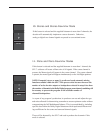
8. Aux IR Receiver
The Aux IR Input is a miniature mono phone jack connector. This is used to connect externally mounted IR
LED receivers, or other extenders that provide modulated IR receiver data. Data is retransmitted by an IR LED
mounted near the front panel IR receiver.
9. RS-232 connector
This connection provides for control of a Bryston SPV-1 video switcher, or remote control of the SP1.7 functions
via a computer interface or AMX/Crestron type controller. Please contact your dealer or Bryston to make use of
this optional feature and determine which devices are compatible.
14
Figure 9: Trigger Assign Menu