


6
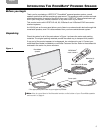
I
NTRODUCING THE ROOMMATE
®
POWERED SPEAKER
EnglishFrançais Español
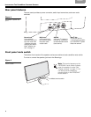
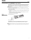
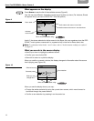
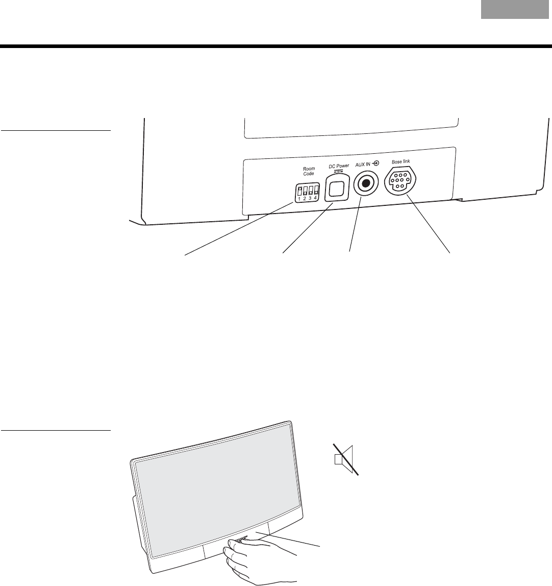
Rear panel features
The rear panel provides a power connector, audio input connectors, and room code
switches.
Figure 2
RoomMate
®
speaker rear
panel
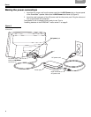
DC Power
A DC power input
jack which accepts
the power pack
output cable.
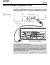
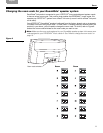
Room Code
Four miniature
switches used to set
the room code. See
“Changing the room
code for your Room-
Mate
speaker sys-
tem” on page 11.
AUX IN
A 3.5 mm (
1
/
8
”) stereo in-
put jack for connecting
an external audio source
(local source).
Bose
®
link
A multi-pin jack for
connecting your speaker
to a LIFESTYLE
®
system
Bose link network.
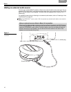
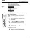
Front panel mute switch
The bottom front center of the speaker enclosure contains a touch-sensitive mute switch.
To mute or unmute the speaker, just touch the Bose logo.
Figure 3
RoomMate speaker mute
switch location
Mute/unmute switch
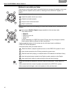
Note: This symbol appears on the
PERSONAL
®
music center II display
when the speaker is muted. See
“Display symbols” on page 15. You
can also mute the speaker by
pressing Mute on the PERSONAL
®
music center II.