


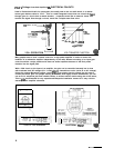
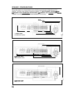
AMPLIFIER CONNECTIONS AND INTERFACE
.
.
1.
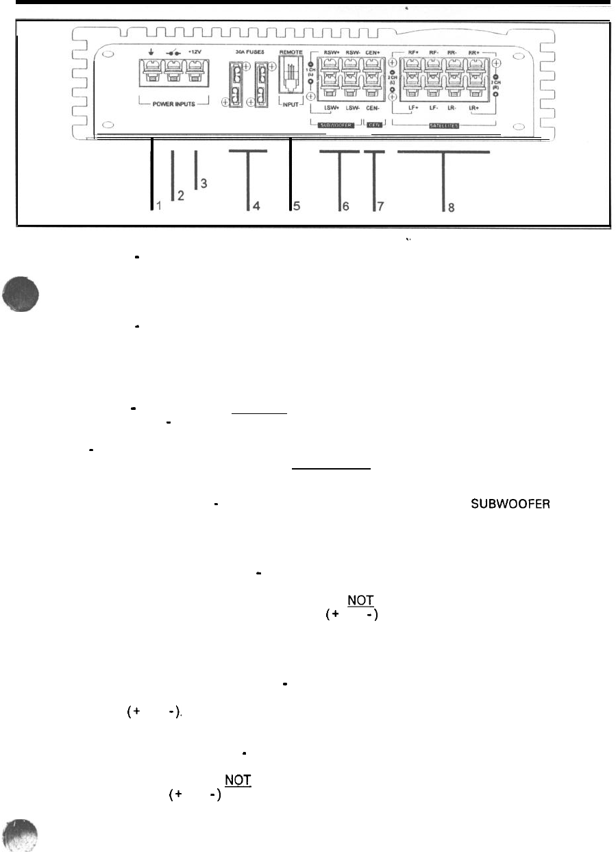
GROUND LINE
-
This is the high current ground connection to the chassis of the car. It should be
fastened to a clean ground connection in the car, capable of handling high current loads. Do not
run a wire up to the car battery ground for this line. It should remain less than 3 feet in length
(Imeter).
2.
3.
4.
5.
6.
7.
8.
TRIGGER LINE
-
This connection is the connection point that allows the amplifier to be switched on
from a remote location (usually the radio). When a positive voltage is applied to this terminal the
amplifier will switch on. This connection is normally made from the power antenna lead of the
radio or a dedicated trigger line. It will turn the amp on for any voltage above 10 volts. Make sure
the radio’s power antenna lead is activated only when the radio is turned on.
BATTERY LINE
-
A high current, fused line should be connected at this point with battery level
voltages (typical 12.5
-
14.5 V DC) available 24 hours a day.
FUSES
-
These fuses are only for catastrophic situations should the amplifier begin to self
destruct. Another fuse should be located at the batterv before a run of wire is run the length of
the car to the remote location of the amplifier.
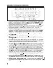
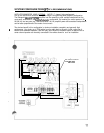
REMOTE CONTROL INPUT
-
This amplifier has the capability to have its SU8WOOFER channel
gain changed from a remote gain control (optional) and uses a standard RJ-1 1 telephone jack
for interface. The HUSH control on the remote controls the HUSH noise reduction for the
Satellite and Subwoofer channels.
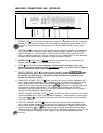
SUBWOOFER SPEAKER OUTPUTS
-
These connections are used to connect loudspeakers with 1
ohm or higher speaker impedance in the 7 channel mode. If any channels are placed into bridge
mode, speaker loads seen by these channels should NOJ be less than 4 ohms impedance.
Please be sure to note the proper wiring polarity
(
+
and
-
)
and take care to verify the proper wire
configurations for bridge mode operation. It is imperative these speaker lines NEVER be
connected or touch the chassis of the car in any way! Speaker wire gauges of up to 8 gauge in
size can be accommodated by these terminals.
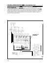
CENTER CHANNEL SPEAKER OUTPUT
-
These connections are used to connect the Front-Center
channel loudspeaker with 2 ohm or higher speaker impedance.
Please be sure to note the proper
wiring polarity
(
+
and
-
).
It is imperative that these lines NOT be connected or touch the chassis
of the car in any way!
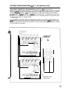
SATELLITE SPEAKER OUTPUTS
-
These connections are used to connect loudspeakers with 1
ohm or higher speaker impedance. If any channels are placed into bridge mode, speaker loads
seen by these channels should
NOT
be less than 4 ohms impedance.
Please be sure to note the
proper wiring polarity
(
+
and
-
)
and take care to verify the proper wire configurations for bridge
mode operation. It is imperative that these lines NOT be connected or touch the chassis of the car
in any way! Speaker wire gauges of up to 8 gauge in size can be accommodated by these
terminals.