


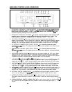
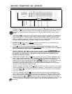
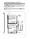
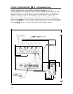
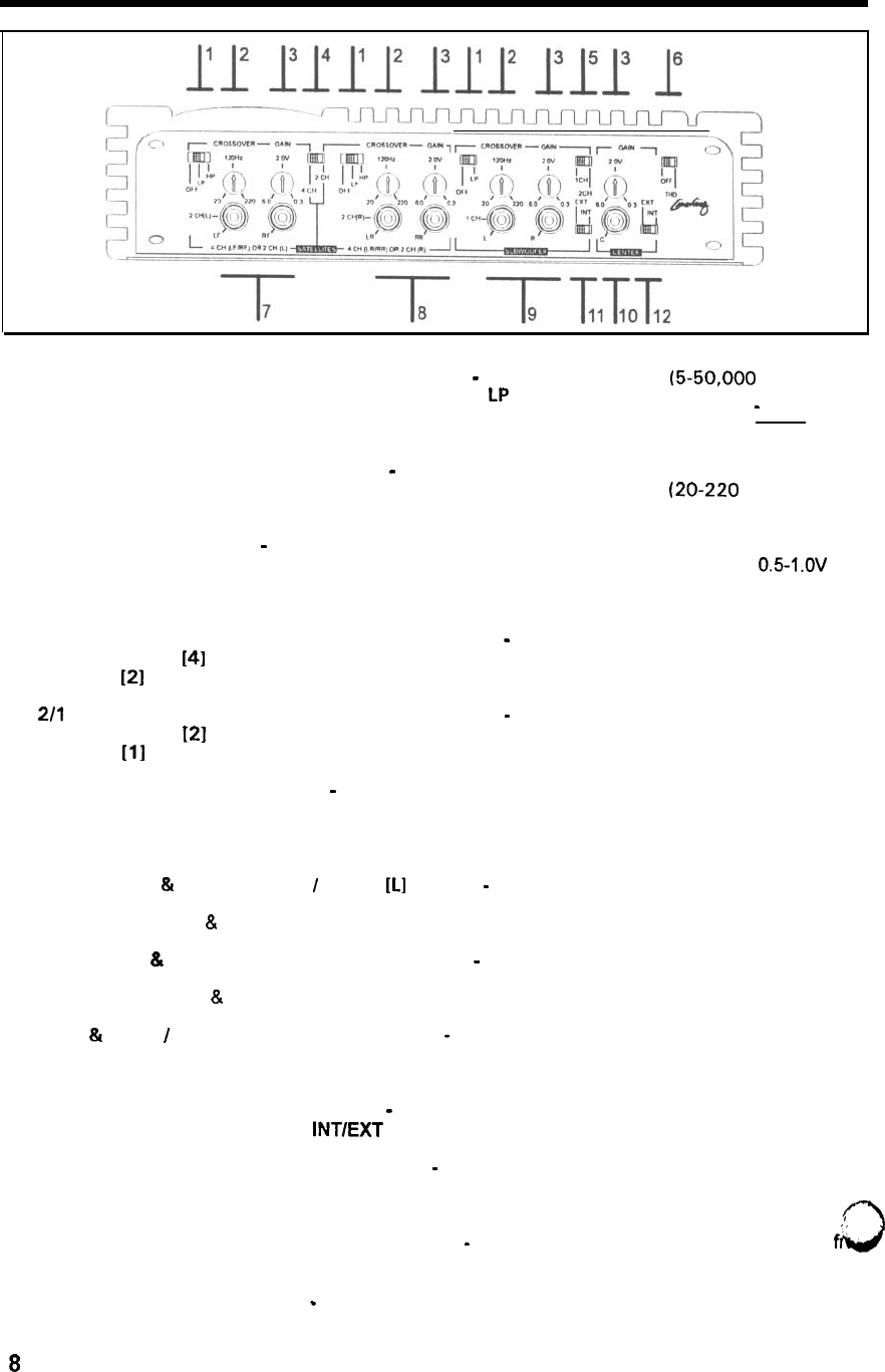
AMPLIFIER CONTROLS AND OPERATION
1.
2.
3.
4.
5.
6.
7.
8.
9.
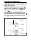
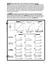
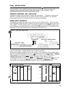
CROSSOVER FREQUENCY CONFIGURATIONS
-
In the full-range mode
(5-50,000
Hz) the amp
reproduces all frequencies heard by humans.
(bass) comes out of the speakers.
In the
LP
(low-pass) position, only low frequency
In the HP (high-pass) position, only information above the
crossover frequency setting is sent to the speakers.
_
3
CROSSOVER FREQUENCY SETTINGS
-
The internal crossover frequency control setting of the
amplifier can be continuously variable within the frequency limits shown
(20-220
Hz). This
control operates in both the LP (low-pass) and HP (high-pass) modes.
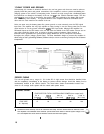
INPUT GAIN CONTROLS
-
This control matches the radio or preamp output voltage to the
amplifier’s input voltage so that full output can be achieved. Most radios provide only
05l.OV
rms
output at their RCA leads. Turning the control clockwise makes the amp play louder. Technically
speaking, this is the voltage needed on the input of the amplifier in order to drive it to full output.
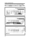
412 SATELLITE CHANNEL MODE SELECT SWITCH
-
For 4 channel operation this switch
should be in the
f41
position. To bridge channels for higher power operation, this switch should
be in the
[21
position.
2/l
SUBWOFER CHANNEL MODE SELECT SWITCH
-
For 2 channel operation this switch
should be in the
121
position. To bridge channels for higher power operation, this switch should
be in the
ill
position
DISTORTION LIMITING ON/OFF
-
When turned on, this control enables the THD, circuit. When
switched ON the circuit greatly reduces all distortion products at high levels but is electrically
transparent at all other listening levels. In the OFF (bypass) mode, the distortion limiting feature
is disabled so typically unwanted clipping harmonics pass on to the speakers.
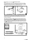
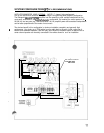
LEFT FRONT
&
RIGHT FRONT
I
MONO
[Ll
INPUTS
-
These lines connect to the RCA output jacks
of a radio, or directly from the high level audio outputs from a radio.
mode these are LF
&
RF.
In the 4 channel satellite
In the 2 channel mode the input marked [L] drives the 2 CH [L] output.
LEFT REAR
&
RIGHT REAR 7 MONO [R] INPUTS
-
These lines connect to the RCA output jacks
of a radio, or directly from the high level audio outputs from a radio.
mode these are LR
&
RR.
In the 4 channel satellite
In the 2 channel mode the input marked R drives the 2 CH [R] output.
LEFT
81
RIGHT
/
MONO SUBWOOFER INPUTS
-
These lines connect to the RCA output jacks of a
radio, or directly from the high level speaker outputs from a radio.
In the 2 CH mode these are L
and R. In the 1 CH mode the L jack becomes the only input but drives both speaker outputs.
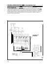
10. EXTERNAL CENTER CHANNEL INPUT
-
If a dedicated center channel signal is desired, it will be
sent in over this RCA jack. The
INTIEXT
switch must be in the EXT position for this to work.
11. INTERNAL/EXTERNAL SUBWOOFER INPUT
-
The subwoofer signal will be derived from the four
RCA inputs unless this switch is in the EXT position where it must have external signal inputs to
operate.
,0
12. INTERNAL/EXTERNAL CENTER CHANNEL INPUT
-
The center channel signal will be derived
fr@
the LF and RF front RCA inputs. In the EXT position it must have external signal inputs to
operate.
.
8