


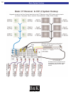
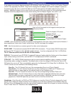
Placement and Ventilation
The CT Receiver incorporates built in power amplifiers and requires at least 3" of free air space above the
unit. If built into a rack, please insert at least one rack space of vent panel immediately above the unit.
Default Operation
The factory default of a B&K CT Receiver is designed for simplicity and functionality right out of the box!
Default settings will allow for simple functions such as zone power, volume control, input changing and video
connections to be checked as soon as they are connected. No programming required!
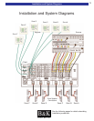
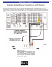
Connection Strategy
Connecting a CT Reciever can be a daunting task at first glance. However, the secret to a great looking and
easy to service installation is to be as deliberate as possible. Make the installation SERVICEABLE as well as
neat! Dress the wires in groups according to purpose:
·AC Power lines tied together and attached to the cabinet/rack on the opposite side of the signal
cabling. Any component without enough slack in the power wire to enable rotating it or extracting it
should have its length extended with a dedicated extension cord.
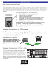
·Speaker wires tied together and attached to the cabinet/rack on the opposite side of AC Power lines.
·Antennas should be routed so that they can be positioned later.
·IR emitters should be routed and tied down, but NOT attached to source components. Remember,
emitter position is best done with the system powered up! Emitter wires can safely be run adjacent to
AC Power cables.
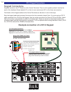
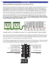
·Combine Keypad/IR Sensor cables together with any Dedicated Zone Input cables that originates in
another zone. Tie each Zone Control cable together with its dedicated source. Tie everything
together; make sure there is a service loop of free cable and dress on the opposite side of the AC
Power cables.
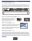
·Combine all cables coming from the sources, label each cable and connect them to the nine inputs.
·Combine all buffered outputs and connect to additional preamplifiers/receivers in the system.
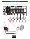
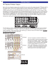
·If you are utilizing any external power amps, combine the zone line outputs and connect to each
amplifier in turn.
Always leave enough slack in the ends of the cable so that the CT Receiver can be rotated in its shelf or
pulled out of the shelf. Don't leave all the wires tied down so tightly that the components cannot be rotated or
extracted from the rack without huge difficulty.
Installation Considerations
BK&
SBIMPLY ETTER!
11
Installation Considerations
CAUTION
RISK OF ELECTRIC SHOCK
DO NOT OPEN