


16
4.1.2 LED-Display
7
9
12
14
81317
18
10
11
15
16
2019
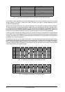
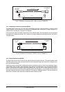
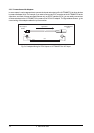
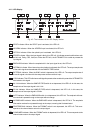
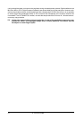
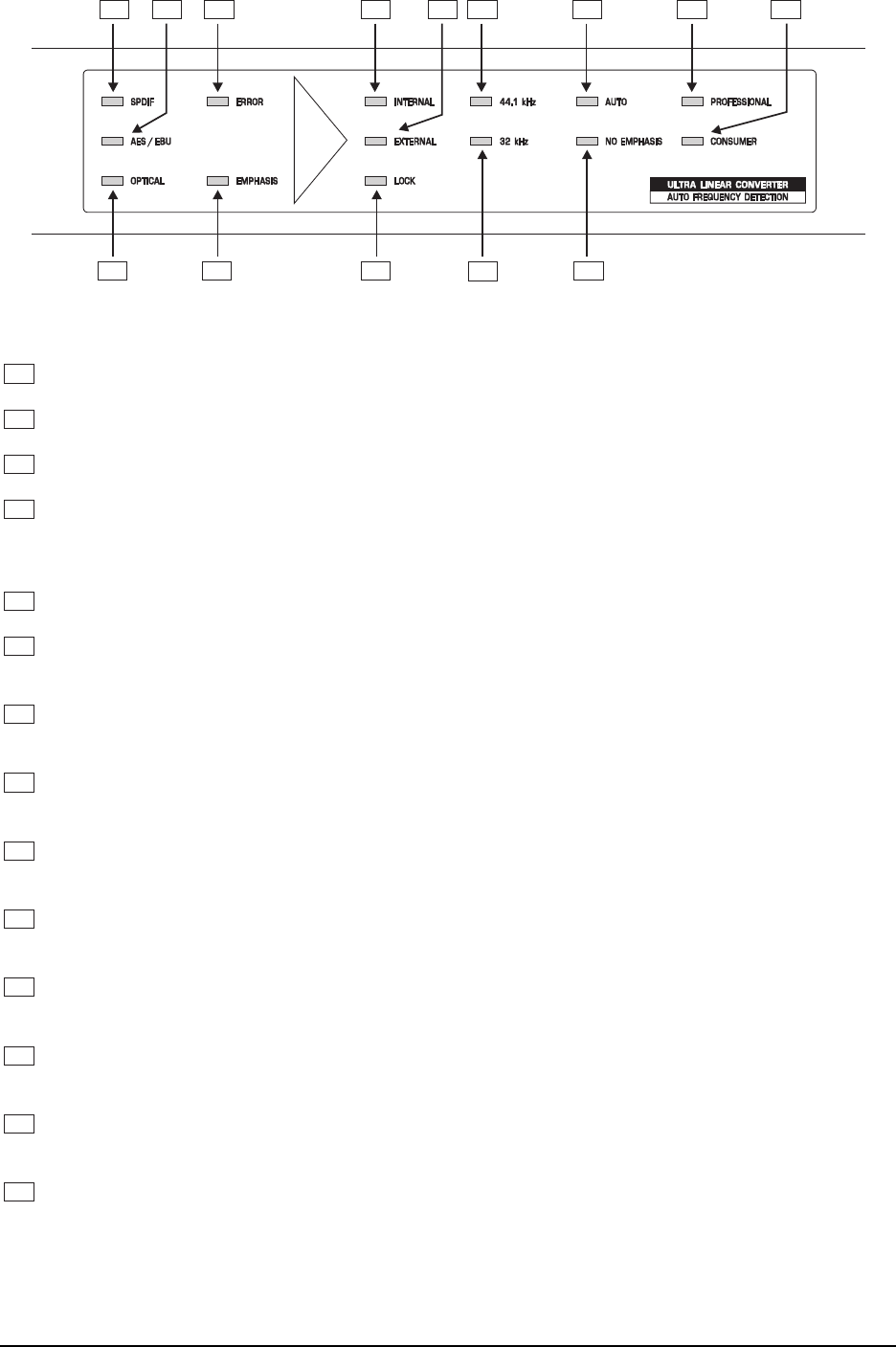
Fig. 4.3: The Indicators of the LED Display Section
7
SPDIF Indicator. When the SPDIF input is activated, this LED is lit.
8
AES/EBU Indicator. When the AES/EBU input is activated, this LED is lit.
9
OPTICAL Indicator. When the optical input is activated, this LED is lit.
10
ERROR Indicator. When the input signal is faulty, this LED is lit. It indicates several malfunctions such
as No Lock, Parity, CRC, Valid, etc. When the LED is lit, the ULTRAMATCH is unable to process the
input signal.
11
EMPHASIS Indicator. When the emphasis bit in the input signal is set, this LED is lit.
12
INTERNAL Indicator. When internal synchronization is activated, this LED is lit. The output sample rate
of the audio signal can be selected with the SAMPLE FREQ switch.
13
EXTERNAL Indicator. When the SYNC switch is depressed, this LED is lit. The output sample rate of
the audio signal coincides with the rate present at the wordclock input.
14
LOCK Indicator. This LED is lit when a valid signal is present at the wordclock input and the ULTRAMATCH
has locked to this signal.
15
44.1 kHz Indicator. When the SAMPLE FREQ switch is not depressed, this LED is lit. In this case, the
sample rate of the output signal is 44.1 kHz.
16
32 kHz Indicator. When the SAMPLE FREQ switch is depressed, this LED is lit. In this case, the
sample rate of the output signal is 32 kHz.
17
AUTO Indicator. When the EMPHASIS switch is not depressed, this LED is lit. The emphasis informa-
tion received is passed through to the output without change.
18
NO EMPHASIS Indicator. When the EMPHASIS switch is depressed, this LED is lit. The emphasis
information received is not passed through to the output, meaning that it is deactivated..
19
PROFESSIONAL Indicator. When the FORMAT switch is not depressed, this LED is lit. This corre-
sponds to the channel status set on the output signal.
20
CONSUMER Indicator. When the FORMAT switch is depressed, this LED is lit. This corresponds to the
channel status set on the output signal.
4. CONTROLS AND FUNCTIONS