


8
ULTRAGRAPH DIGITAL DEQ1024
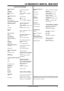
2. CONTROL ELEMENTS
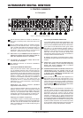
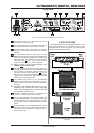
Fig. 2.4: Input/output wiring depending on operating mode
BAAAAA
CAAAAA
CBAABA
BABAAB
Tab. 2.1: Input/output wiring depending on
operating mode
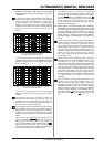
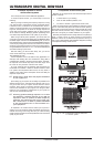
Fig. 2.5: Signal flow in PRE EQ mode
Fig. 2.6: Signal flow in POST EQ mode
When you keep the CLOCK switch depressed for a few
seconds, you can select the desired sample rate with
which your DEQ1024 is working: 44.1 kHz, 48 kHz or
96 kHz (green LEDs). To synchronise your DEQ1024 with
the sample rate of an external unit (e. g. through a digital
mixing console), you have to select the DIG IN setting
(yellow LED lights up).
+ If you select the DIG IN setting, although no signal is
connected to the digital input, the DEQ1024 is not
able to synchronise with any sample frequency
(yellow DIG IN LED is blinking). In this case the
ULTRAGRAPH DIGITAL switches to the sample
frequency last connected to the digital input. If you
connect a signal to the digital input while operating
in the unsynchronised mode, your DEQ1024
switches back to normal mode and synchronises
with the connected sample frequency (yellow LED
lights up).
To select the word length of the digital output signal
(16 bit or 24 bit), keep the CONFIG and CLOCK
switches simultaneously pressed. The 24-bit
setting is shown by means of the -24 dB LEDs in the
METER display (see
). When the 16-bit setting is
selected, no METER LED lights up. This way, the
DEQ1024 can be adjusted to the 16-bit inputs of DAT
and CD recorders or sound cards. The analog
output signal is always converted with 24 bit,
independent of the above setting.
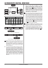
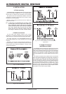
The 12-digit LEVEL METER shows the signal level of the
input and output signals. Use the METER switch located
below it to select the respective signal, whereby the output
signal is indicated when the switch LED lights up (green),
and the input signal is indicated when the switch LED is not
lit. The red CLIP LED lights up as soon as the indicated
signal is overdriven. The GATE and the LIMITER LED
shows that the threshold of the respective dynamics
processors is either exceeded or is below the selected
value; the LED also indicates that the dynamics processor
is active at this time (see ). Additionally, the volume of
the pink noise generator and the 24-bit word length setting
(see ) is shown on the LED METER.
Keeping the STANDBY switch depressed for a few
seconds puts the DEQ1024 into standby mode (red switch
LED lights up). In this case, the signal connected to the
DEQ1024 is looped through without being processed.
+ All new settings are saved after approx. 2 seconds,
so that powering the DEQ1024 off and then on again
(by using the STANDBY or the POWER switch on
the rear panel) recalls the current settings.