


7
ULTRAGRAPH DIGITAL DEQ1024
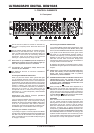
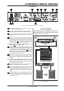
2. CONTROL ELEMENTS
+ Try to orient yourself on a frequency whose signal
level lies in the 0 dB to -3 dB range in order to avoid
overdriving the equipment connected (e. g. amp,
crossover).
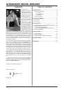
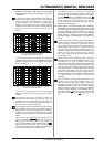
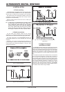
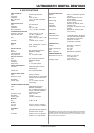
In the world of ordinary graphic equalizers, there is always
a difference between the adjusted curve and the resulting
frequency response. This phenomenon is simply caused
by the construction of such equalizers. This difference
depends on the frequency and its cut/boost. Near-by
frequency bands influence one another, whereby individual
instances of cut or boost can also be added up to one
another.
Fig. 2.2: Graphic equalizer without
frequency response correction
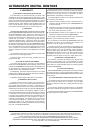
This occurrence can be corrected by means of a specially
developed algorithm utilized in the ULTRAGRAPH DIGITAL
DEQ1024. Simply press the TRUE CURVE switch (green
switch LED lights up).
Fig. 2.3: Graphic equalizer with frequency response
correction (TRUE CURVE)
The resulting frequency response now corresponds
exactly to the settings that you adjusted with the graphic
equalizer.
The BYPASS switch lets you directly compare the
processed and unprocessed audio program. When the
BYPASS function is activated (red switch LED lights up),
the input of the unit is directly forwarded to the output so
you can monitor the unprocessed signal.
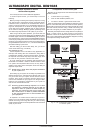
The DYNAMICS section of the DEQ1024 consists of a GATE
and a LIMITER. Use the GATE and LIMITER controls to
determine the threshold. When the threshold is exceeded
(LIMITER) or when the signal falls below the threshold
(GATE), the dynamic processors starts affecting the signal.
GATE
When the input signal falls below the threshold value, the
signal is completely faded out. Tape hiss, crosstalk or
disturbing noise can thus be effectively removed from the
signal. The yellow GATE LED in the METER section (see )
lights up as soon as the GATE closes. The range of the
threshold lies between -60 and -10 dB. When turned all the
way to the left, the GATE is deactivated (OFF).
LIMITER
The LIMITER protects your equipment from signal peaks
that could for example damage your speakers. Output signal
levels that exceed the selected threshold value are limited,
and the red LIMITER LED in the METER section (see
)
lights up. By reducing signal dynamics, a more expressive
sound is achieved. The threshold range lies between
-6 and +9 dB. When turned all the way to the right, the
LIMITER is deactivated (OFF).
+ Please keep in mind that boosting many frequency
bands also increases the output signal level. In this
case, the limiter is activated sooner. You can avoid
this by achieving signal correction not only by
boosting frequency bands but by also lowering
signal levels. To achieve creative sound effects,
the peak limiter can deliberately be driven to its
limits.
The DEQ1024 features a LOW CUT and HIGH CUT filter in its
FILTER section, allowing you to limit the entire frequency
spectrum upward or downward. The HIGH CUT control is
used to determine the cut-off frequency above which the
high frequency range is lowered (2.5 - 16 kHz). When turned
all the way to the right, the filter is deactivated (OFF). The
LOW CUT control is used to determine the cut-off frequency
above which the low frequency range is lowered
(20 - 160 Hz). When turned all the way to the left, the filter
is deactivated (OFF).
Use the GAIN control in the MASTER section to determine
the output volume of the ULTRAGRAPH DIGITAL in the
range between -9 to +9 dB. In addition, there is also a
stereo imager function that lets you adjust the stereo width
and therefore the separation between the left and the right
stereo side. When the STEREO IMAGE control is turned
all the way to the right, you achieve the maximum widening
of the stereo signal (WIDE); when the control is turned all
the way to the left, the stereo signal is transformed into a
mono signal (MONO). When the STEREO IMAGE control is
in its middle position, your signal is not processed
(STEREO).
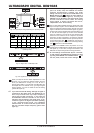
When you keep the CONFIG switch depressed for a few
seconds, you can select the operating mode of your
DEQ1024: ANALOG (green LED), DIGITAL (yellow LED),
PRE EQ (yellow LED) or POST EQ (yellow LED). When in
the PRE EQ or POST EQ mode, you can use the rear panel
digital connectors as inserts, for example for an additional
dynamics processor. When the unit is in PRE EQ mode, the
insert point is located pre EQ; when the unit is in POST EQ
mode, the insert point is located post EQ (see fig. 2.5 and
2.6).