


28
TUBE COMPOSER T1952
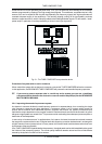
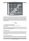
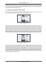
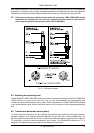
Fig. 4.6: Pentode
In a triode the capacitance between grid and anode is a problem with regard to high frequencies and large
amplification factors. For this reason, the pentode has a positively charged screen grid between the control grid
and the anode. However, the positive charge of the screen grid attracts electrons emitted from the anode plate
when it is hit by arriving electrons. To prevent this electron emission, a decelerating or suppressor grid is
placed between anode and screen grid. As it is negatively charged it blocks the electrons, so that they cannot
reach the screen grid. Pentodes are most commonly used in power stages.
4.5 Properties of tubes
In general, the saturation (overdriving) of both transistor and tube-based circuits results in various types of
distortion. These phenomena are quite complex in the real world, but for the sake of a straightforward
mathematical description we are going to classify them as linear and non-linear distortion. Linear distortion is
produced by frequency-dependent amplification or attenuation processes such as occurs in all kinds of filters
and equalizers. Linear-distortion signals have the same frequency portions both on the input and output sides,
but with different phase positions and amplitudes. Non-linear distortions have additional harmonics and distor-
tion components that were not contained in the original input signal.
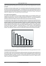
For example, when the plainest of all oscillations, a sine wave with a fixed frequency f, is overdriven, new
oscillations with frequencies of 2*f, 3*f, etc. (integral multiples of the original frequency) are produced. These
new frequencies are referred to as upper harmonics grouped as odd and even harmonics. Unlike the transistor,
saturated tubes mostly produce even harmonics which are perceived by the human ear as more pleasant in
sound than odd harmonics. Another important aspect lies in the fact that tubes produce distortion more
gradually than transistors, which is why we speak of the saturation of a tube stage. When you overdrive a
transistor you get a sudden square deformation of the sine signal applied at the input, which produces an
extreme harmonic spectrum at the output.
Non-linear distortions are measured with a distortion factor that consists of the total harmonic distortion [k] and
partial harmonic distortions [kn]. The latter are defined as the ratio between the voltage of a single harmonic
and the voltage of the distorted overall signal. Thus, the content of even harmonics is expressed as k2, k4, ...
and that of odd harmonics as k1, k3, ...
k
U
U
n
n
ges
=
Formula for calculating partial harmonic distortion
The total harmonic distortion is the root of all squared distortion factors of the second and third degrees. Since
the higher harmonics have only little impact on the measured results, they can be neglected.
kkk=+
2
2
3
2
Formula for calculating total harmonic distortion
In tube circuits the distortion factor k2 is used to describe an effect which the human ear classifies as
pleasant. Also the frequency bands in which distortion occurs play an important role because the human ear
differentiates very clearly in the frequency range of human speech.
4. TECHNICAL BACKGROUND