


11
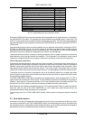
TUBE COMPOSER T1952
26
28 30
31292725
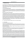
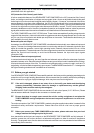
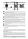
Fig. 1.4: Back panel of the TUBECOMPOSER
25
SERIAL NUMBER. Please complete and return the warranty card within 14 days of the date of
purchase. Otherwise, you will lose your right to the extended warranty. Alternatively, you can register
online at our website under www.behringer.com.
26
FUSE HOLDER / VOLTAGE SELECTION. Before connecting the T1952, confirm that the voltage
display matches your local mains voltage. When replacing the fuse, you must always use the same
type. In many units the fuse holder can be installed in one of two positions, allowing you to switch
between 230 V and 115 V. If you wish to operate a unit outside Europe at 115 V, then a stronger fuse
must be used (see chapter 6 SPECIFICATIONS). The mains connection is made via the IEC
receptacle. An appropriate mains cable is included.
27
AUDIO IN. These are the audio inputs of your TUBE COMPOSER, available both as balanced 1/4" TRS
and XLR connectors. Both the XLR and the jack connector accept unbalanced as well as balanced
signals. See chapter 5 INSTALLATION when wiring unbalanced.
28
AUDIO OUT. These are the audio outputs of your TUBE COMPOSER, which are also designed as
1/4" TRS and XLR sockets. The automatic servo function recognizes balanced or unbalanced
connection and automatically compensates for the difference in level (correction 6dB). These outputs
can be transformer-balanced by retrofitting the optional output transformer OT-1.
29
With the OPERATING LEVEL switch you can adapt the TUBECOMPOSER to various operating levels,
i.e. you can select both the -10dBV home recording level and the professional studio level of +4dBu.
The level meters are referenced automatically to the selected level, i.e. an optimum operating range of
the meters will always be ensured.
30
SC SEND. This is the unbalanced side chain output which allows for routing the audio signal to external
processing devices.
31
SC RETURN. This is the unbalanced side chain input used to return any external or processed control
signal. Please note that the side chain signal is only the control signal. The unbalanced connection
therefore does not represent any danger for your audio signal.
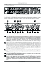
2. OPERATION
In this section, several typical applications of the BEHRINGER TUBECOMPOSER are discussed. The
following basic settings can resolve most dynamic problems. They are the ideal starting point. Please take the
time to study the application examples carefully, in order to be able to make full use of the TUBECOMPOSERs
capabilities in the future.
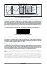
Main applications and initial settings
The main applications of the BEHRINGER TUBECOMPOSER can be divided into three categories: The
expander/gate section is used to eliminate interference and to suppress background noise and leakage on
individual tracks in multitrack recording. The compressor section is used to compress the program material
and to create special effects and unusual sounds, which are used for recording and musical performance. The
subsequent peak limiter section is designed to protect loudspeakers, tape recorders, transmitters etc. from
being overloaded.
2. OPERATION