


16
TUBE COMPOSER T1952
Output
Input
Peak Limiting
Program Limiting
Release
Threshold
t/ms
Level
20 ms
10 20 30
5 ms
approx. 1 s
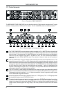
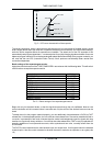
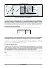
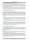
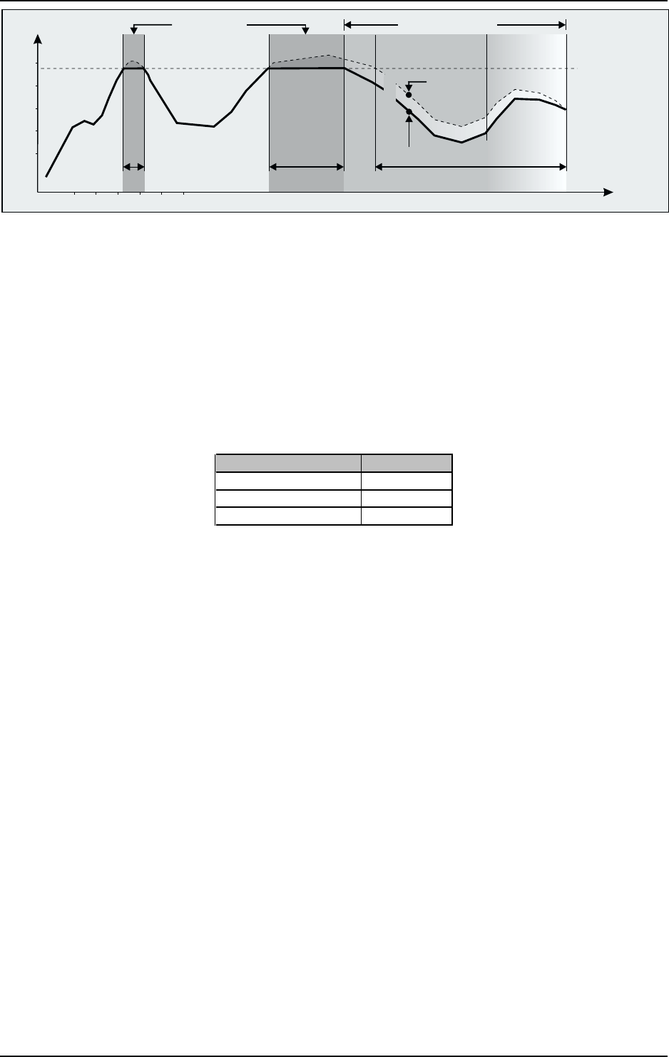
Fig. 2.3: IGC characteristic of the limiter section
The diagram illustrates the functioning of the IGC limiter. The solid graph represents the output signal, while the
dashed graph above shows the input signal response. The areas between the graphs represent the amount of
gain reduction (bright areas are clipping areas, i.e. signal peaks are radically cut off, dark areas show the
effect of the program limiter). The limiter is activated when the adjusted threshold is exceeded for more than
20 ms, so as to limit audible clipping to a very short moment. About 1 s after the signals has dropped below the
threshold again, the reduction is set to 0dB, so that input and output signals are identical again (unity gain).
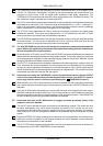
Basic settings of the peak limiter section
This is a good starting point for the peak limiter. The settings for the compressor can remain unaltered.
Control element Setting
IN/OUT switch IN
SC MON switch OFF
LIMITER control OFF
Tab. 2.3: Basic settings of the peak limiter section
With the LIMITER control you can guard subsequent electronics against overload. The LIM LED shows when
the limiter is active. When this LED lights up often, reduce the OUTPUT level in the compressor section.
If this results in an unwanted reduction of the sound pressure level it is also possible to increase the
compression. You can do this by either lowering the threshold or increasing the compression ratio. After that,
you can set the desired loudness using the OUTPUT control.
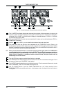
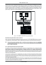
2.5 The side chain function
The BEHRINGER TUBECOMPOSER offers an exceptionally usable external facility by using the side chain
function. By activating the SC EXT switch, the TUBECOMPOSERs control path is disconnected from the
audio input and therefore interrupted. The audio input is routed to the SC SEND output and the SC RETURN
input now receives the new control signal which is derived from an inserted effects processor.
Please ensure correct wiring for mains powered units in order to avoid ground loops, as the side chain inputs
and outputs are unbalanced. The operating level of external units must be at line level (-20 to +10dBu/unity
gain).
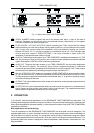
It is very common to make the response threshold of a compressor frequency-dependent, where a graphic or
parametric equalizer is connected to the side chain path. To retain the threshold setting of the
TUBECOMPOSER, unwanted frequencies should be reduced by an equalizer and the desired frequencies
should be kept at the same level. Should for example, the compressor be controlled by a narrow mid-frequency
band, it is advisable to lower the bass and treble controls. The middle frequency control remains at unity gain.
2. OPERATION