-7-
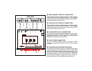
OPERATING INSTRUCTIONS
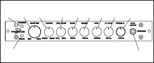
1 POWER INDICATOR
This LED indicator lights green when power is applied to the
unit from a remote source, such as the radio and/or the vehicle
ignition switch, and provided the remote terminal is connected
to +12Vdc.
2 PEAK INDICATOR
This LED indicator lights red when the equalizer input signal
exceeds the input range, thereby causing saturation or over-
loading to take place. The indicator will also light when the
input signal itself is overdriven or clipped.
3 MASTER MIN/MAX CONTROL
Rotate this control clockwise (MAX) or counterclockwise
(MIN) to adjust the overall system volume after the source
radio or amplifier volume output has been set to the desired
level.
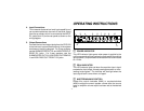
1
2
3
4
567
8
9
10
11
4.
Input Connections
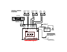
This crossover features low-level input capability and
can accommodate two channels of low-level output
from the car stereo, which is connected to the INPUT
R/L jacks (item 12) on the rear panel as shown on the
wiring diagram.
5.
Output Connections
Connect the low-level output jacks from the PEQ-200
to the low-level inputs of the amplifier(s) in the system
as shown on the wiring diagram. For 2-way systems,
use the SUBWOOFER OUT R/L and HIGH PASS OUT
REAR R/L jacks. For 3-way systems, use the
SUBWOOFER OUT R/L, HIGH PASS OUT REAR R/
L and HIGH PASS OUT FRONT R/L jacks.


