


-5-
NOTE: If ground wire to the source is not available, you will
need to find your own grounding point. Locate a metal
area close to the PEQ-200 that provides a good ground
point (preferably the floor). Eliminate unwanted paint
and other contaminants using a wire brush or sandpa-
per. Terminate the black wire using the correct size of
ring terminal and attach it to the bare metal. Spread
Silicone over the screw and bare metal to prevent rust
and corrosion.
3.
Remote Turn-On Connection
(
Orange wire
)
The PEQ-200 is turned on by applying +12 volts to the
remote turn-on terminal (REM) of the cable 4-Pin
connector harness. The wire lead to this terminal
should be connected either to the "Auto-Antenna"
lead from the car stereo, or to some other point which
will provide a +12 V dc supply only when the car
stereo is turned on. If the car stereo does not provide
an Auto-Antenna lead, the remote turn-on lead may be
wired to an "Accessory" or "Radio" terminal in the car's
fuse block. This will turn the PEQ-200 on and off with
the ignition key, regardless of whether the car stereo
is on or off. The remote turn-on lead of the cable
harness does not have to carry large currents, so #20
gauge wire may be used for this application. After the
remote connection has been made, insert the cable
connector into the 4-pin jack at the rear of the unit while
pressing the key tab; it will snap into place.
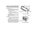
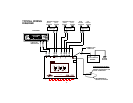
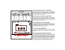
WIRING INSTRUCTIONS
The wiring of your crossover equalizer will depend on the
system and speakers you are using but will either be a 2-way
(bass and midrange/high) or 3-way (bass, midrange and high)
application using 2 or 4 channels of input from the car stereo.
The following pages illustrate the input and output wiring for
these types. Please refer to the appropriate diagram for the
system configuration you are using.
The power connections for this unit are accomplished using the
supplied modular 4-pin connector wiring harness (item 18). The
wiring harness contains three color-coded wires.
Connecting these wires should not be overly difficult if the
following guidlines are adhered to: (See the installation dia-
gram.)
1.
Power Connection
(
Red wire
)
Pull the source unit (radio, amplifier, etc.) out from the
dash far enough until the wires are exposed at the rear
of the unit. Using a digital voltmeter, find a constant
+12Vdc lead for the radio, and splice into this wire.
Splice or solder the red wire from the wiring harness
and connect it inline with the +12Vdc wire using a
barrel connector of appropriate size.
2.
Ground Connection
(
Black wire
)
Locate the ground wire supplied to the source unit and
splice into it. Take the black wire from the wiring
harness and connect it in line with the ground wire by
splicing and or soldering.