


System Operation
Switch on the receiver. Do not switch on the transmitter yet.
Selecting/Setting Frequency
It’s usually best to start by setting the receiver’s frequency to
determine there is no local interference on that frequency.
Then, always make certain to set the transmitter to the receiv-
er’s exact frequency. The receiver’s Tone Lock system squelch-
es the audio only, permitting any RF energy on the frequency to
show on the “RF” bar-meter.
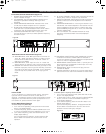
Receiver On…
The Power switch indicator and the LCD window will light up,
the normal-operation LCD display will appear after 1-2 seconds
(Figure D). If any of the bars show in the “RF” bar-graph meter,
there may be RF interference in the area. If this occurs, select
another frequency as explained below.
How to Make Setting Changes
A. Select Frequency Manually
1. From the normal operating mode, press and hold the set
button until display flashes.
2. To select frequency, press CH SELECT/SCAN button once
at a time until desired channel is displayed (1 to 9, A to F).
3. (a) To select frequency, press and hold SET button until
display stops flashing.
(b) To cancel frequency selection, simply press the SET
button once. The receiver then returns
to the normal
operation.
B.
Select Open Frequency Scan Function
1. From the normal operating mode, press and hold the set
button until display flashes.
2. To select scan function, press and hold CH SELECT/SCAN
button, continue to hold until available frequency is
automatically displayed.
3. (a) To select frequency, press and hold SET button until
display stops flashing.
(b) To cancel frequency selection, simply press the SET
button once. The receiver then returns to the normal
operation without making any changes.
Setting Transmitter Frequency
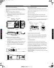
ATW-T161
Slide the Battery cover off and use screwdriver provided to set
the channel switch to the same channel selected on the receiv-
er.
ATW-T162, ATW-T163
While holding the upper part of the transmitter body just below
the ball-screen, unscrew lower body cover, slide downward and
remove to expose battery compartment.
Use screwdriver provided to set the channel switch to the
same channel selected on the receiver.
Receiver Squelch
The 1600 Series employs a Tone Lock squelch system that pro-
vides enhanced rejection of RF interference. The squelch control
on the front panel of the receiver is preset at the factory, but
can be adjusted if you are using the system in a high RF inter-
ference area.
This adjustment
can cause a reduction in the use-
able range of the wireless transmitter, so set the control to the
lowest position which reliably mutes the unwanted RF signals.
Input Level Adjustment
An input trimmer control (Trim) in the transmitters enables you
to maximize performance for a particular microphone or guitar
sensitivity, or to adjust for different acoustic input levels.
Setting Levels
Correct adjustment of transmitter audio input, receiver audio
output, and mixer/amplifier input and output levels is important
for optimum system performance.
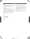
Adjusting Input Level - UniPak Transmitter
Slide the battery cover off the top part of transmitter and
remove the screwdriver from its clip (Figure E). Gently turn the
"MT" (mic trimmer) and "GT" (guitar trimmer) control to their full
counterclockwise positions (marked “Lo”).
• Microphone: Adjusting input level
While speaking/singing into the microphone at typically-loud
levels, carefully turn the MT control clockwise while
watching the receiver’s AF Level indicator. Increase the Trim
control setting until the maximum audio output of the mic
lights about three or four units on the receiver's AF Level
indicator. Do not set the level too high. At normal audio levels,
only the first two or perhaps three units should light.
(When using a microphone, return the
GT control setting to
minimum)
• Guitar/Instrument:
Adjusting input level
While playing at typically-loud levels, carefully turn the GT
control clockwise while watching the receiver’s AF Peak
indicator. Increase the Trim control setting until the maximum
audio output of the mic lights about three or four units on the
receiver's AF Level indicator. Do not set the level too high.
After adjusting input level, return the screwdriver to its clip and
reinstall the battery cover. No further transmitter gain adjust-
ments should be needed, as long as the input device and the
acoustic input level are not changed.
6
CAUTION! The small trimmer controls are delicate; use
only the supplied screwdriver. Do not force the trimmers
beyond their normal 190
o
range of rotation.
Return the screwdriver to its storage clip when not in use.
C
M
J
CM
MJ
CJ
CMJ
N
6.pdf 26/11/08 17:07:34