


Receiver Installation
3
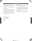
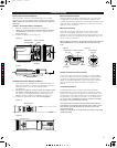
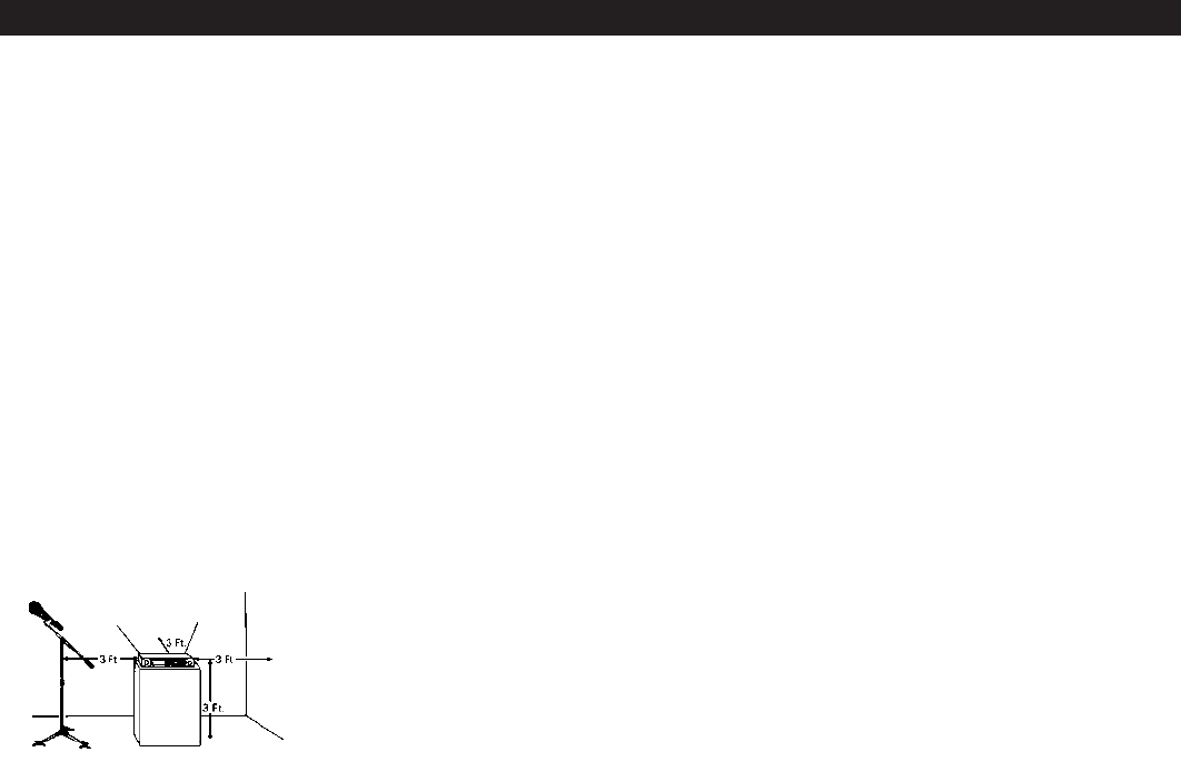
Location
For best operation the receiver should be at least 1 m above
the ground and at least 1 m away from a wall or metal surface
to minimise reflections. The transmitter should be at least 1 m
from the receiver, as shown in Figure A.
Keep antennas away from noise sources such as digital equip-
ment, motors, automobiles and neon lights, as well as large
metal objects.
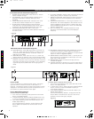
Output Connections
There are two audio outputs on the back panel: balanced
(32 mV) and unbalanced (52 mV). Use shielded audio cable for
the connection between the receiver and the mixer. If the input
of the mixer is a
1
/
4
" jack, connect a cable from the
1
/
4
" unbal-
anced audio output on the back of the receiver housing
to the mixer. If the input of the mixer is an XLR-type input, con-
nect a cable from the balanced XLR-type audio output on the
back panel to the mixer. The two isolated audio outputs permit
simultaneous feeds to both unbalanced and balanced inputs.
For example, both a guitar amp and a mixer can be
driven by the receiver.
Antennas
Attach the included pair of UHF antennas to the antenna input
jacks. The antennas are normally
positioned in
the shape of a
“V” (both 45° from vertical) for best reception.
Antennas can be remotely located from the receiver. However,
due to signal loss in cables at UHF frequencies, use the
lowest-loss RF cables practical for any cable runs over 25 feet
(8 m ). RG8-type is a good choice. Use only copper-shielded
cable, not CATV-type foil-shielded wire. Audio-Technica offers
quality RF cables in four lengths, as well as remote antennas;
see the Optional System Accessories section on page 9.
Power Connections
Connect the supplied AT 220 ~ 240V, 50Hz AC adapter to the
DC power input on the back of the receiver. Operation of the
receiver is controlled by the front-panel Power switch.
Figure A
C
M
J
CM
MJ
CJ
CMJ
N
3.pdf 26/11/08 17:02:18