


Transmitter Setup
Battery Selection and Installation
Each transmitter uses two 1.5V AA batteries, not included.
Alkaline type is recommended. Always replace both batteries.
Make certain the transmitter power is Off before replacing
batteries.
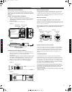
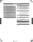
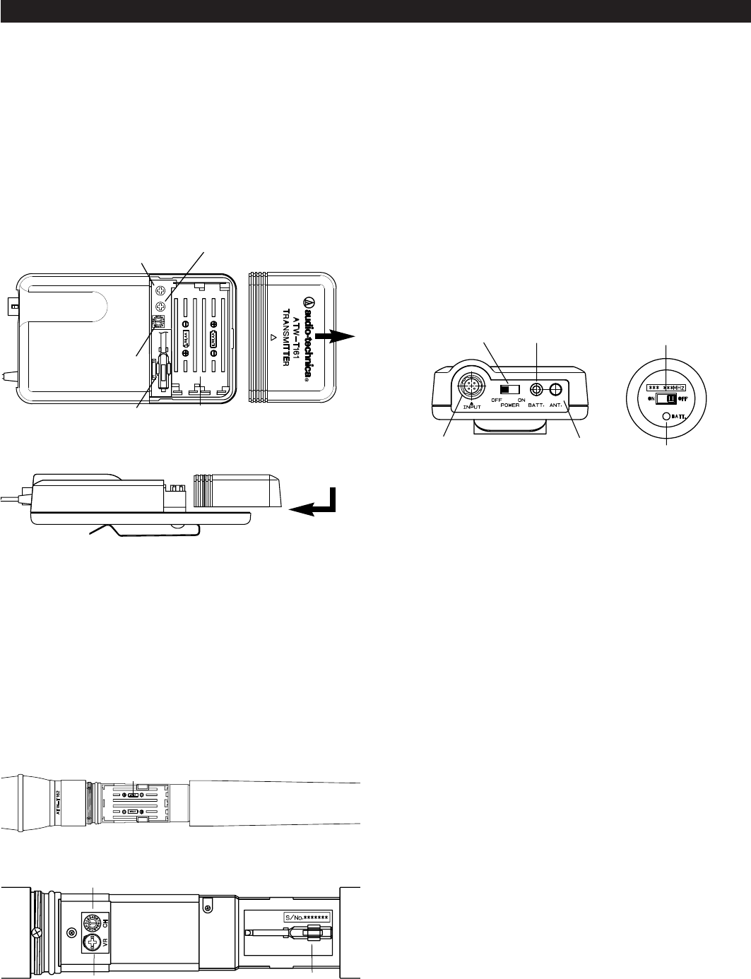
UniPak™ Transmitter Battery Installation
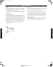
1. Slide off the battery cover as shown in Figure E.
2. Observe correct polarity as marked inside the battery
compartment, and carefully insert two fresh 1.5V AA
alkaline batteries.
3. Replace the Battery cover (Figure.E)
Figure E
Figure F
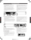
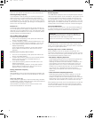
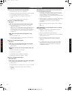
Handheld Transmitter Battery Installation
1. While holding the upper part of the transmitter body just
below the ball-screen, unscrew the lower body cover and
slide downward to remove and expose battery
compartment.
2. Be certain to observe correct polarity as marked inside
the battery compartment (Figure G) and carefully insert
two fresh 1.5V AA alkaline batteries. Make certain the
batteries are fully seated in the battery compartment.
3. Replace the lower body cover. Do not overtighten.
Figure G
Figure H
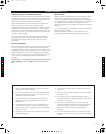
Battery Condition Indicator
The Green Battery condition indicator(Figure I/ J) should light
strongly with a fresh battery. As the battery weakens, the
indicator will glow Red. When the Indicator becomes Red, there
is little life left in the battery. Replace it at once for continued
operation of the transmitter.
Battery Save Switch
ATW-T161 Transmitter features
RF Lo / Hi Power switch
(Figure
E). As supplied, the switch is set in the Lo (Low)
position for the maximum battery life. Hi(High) position can be
selected for maximum range (Note range decreases when the
switch is set at Lo position.)
Special Note: If accessing de-regulated frequencies between
863 to 865MHz(Ch. C to F), ATW-T161 must be set to RF
Low.
J erugiFI erugiF
UniPak Transmitter Input Connection
Connect an audio input device (microphone or guitar cable)
to the audio input connector on the bottom of the transmitter.
A number of Audio-Technica professional microphones and
cables are available separately, pre-terminated with a UniPak
input connector (see “Optional System Accessories” on
page 9).
Transmitting Antenna
The UniPak transmitter includes a permanently-attached
flexible antenna. For best results, allow the antenna to hang
freely and full length from the bottom of the transmitter. If the
received signal is marginal, experiment with different transmit-
ter positions on your body or instrument; or try repositioning
the receiver. Do not attempt to remove, replace or change
the length of the transmitting antenna.
The antenna for the ATW-T162 and ATW-T163 handheld
transmitters are located at the bottom of the units. For
the
best
results, hold the Microphone naturally around the
centre of the body.
Holding or otherwise covering antenna housing may affect
operating range.
5
Battery-Save Switch
(under screwdriver clip)
Guitar Trimmer
(
GT)
Microphone
Trimmer (MT)
Battery Polarity
Diagram
Channel Selector
Battery Polarity
Diagram
Screwdriver
Gain Trimmer
Channel Selector
Battery Condition
Indicator
Power Switch
OFF / ON
Input
Connector
Antenna
Battery Condition
Indicator
Power Switch
ON / OFF
C
M
J
CM
MJ
CJ
CMJ
N
5.pdf 26/11/08 17:03:39