


AMPSUB210
OWNER’S MANUAL
9200 North Decatur St. Portland, OR 97203 • 503.286.9300 • www.audiosource.net
6
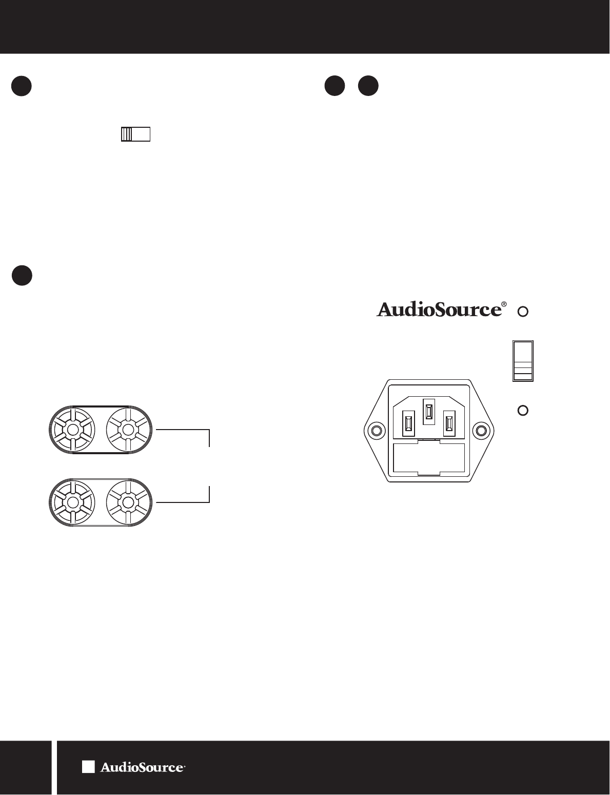
SPEAKER TERMINALS
Terminals are provided for two subwoofers. Connect the speaker’s positive (red)
terminal to the amplifier’s positive (red) terminal, and the speaker’s negative
(black) terminal to the amplifier’s negative (black) terminal.
NOTE: Use the appropriate gauge speaker wire when connecting speakers
to the AMPSUB210.
If using two speakers they must be a minimum of 8 ohms each. DO NOT BRIDGE.
The speaker terminals are internally bridged.
MAINS POWER INLET/FUSE/
VOLTAGE SELECTOR
Power inlet accepts the IEC type line cord supplied with the amplifier. A fuse
in the integrated holder provides safety protection from fault conditions:
replace fuse with one of same type and rating only.
This amplifier is configured for operation at 115V ~60Hz. (North America)
The AMPSUB210 can be configured for operation from either 115V ~60Hz
or 230V ~50Hz AC mains. Installed mains fuse must be of type and rating
marked on amplifier corresponding to configured AC mains voltage.
Should you wish to configure the AMPSUB210 for use 230V ~50Hz
please contact your dealer or distributor.
Figure 8. Speaker Terminals
16
17 18&
LIGHT BAR DISPLAY
15
On Off
Light Bar Display
This switch controls the lighted bars on the front of the amplifier. These bars
light red when the amplifier is in operation. If the amplifier is visible and a low
light setting is desired use this switch to turn off the light bars. The other LED
indicators on the front panel as well as the power button lighted ring are not
affected by this control.
Figure 7. Light Bar Display Control
-
+
-
+
Use Class 2 Wiring
Minimum Impedance:
4 ohms Combined Load
115V~ 60Hz 700W
FUSE:T6.3AL 250V
FUSE:T3.15AL 250V
230V~ 50Hz 700W
MODEL AMPSUB210
Custom Manufactured in China
CAUTION: See User Manual Before
Replacing Fuse
Figure 9. Mains Power Inlet/Fuse/Voltage Selector