


AMPSUB210
OWNER’S MANUAL
9200 North Decatur St. Portland, OR 97203 • 503.286.9300 • www.audiosource.net
5
FRONT PANEL CONTROLS
The front panel power switch switches the AMPSUB210 on or off. Red
LEDs behind the power button lens indicate power status. Whenever
the amplifier’s power switch is in the “ON” position and the amplifier is in
“Active” status the Signal LED is illuminated green. If the amplifier
is “ON” but in “Standby” status the Signal LED will illuminate orange.
REAR PANEL CONTROLS
The AMPSUB210 can be turned on and off independently via the power
switch on the front panel, by signal sensing, or remotely by a triggered
DC input. Switch
14
, located on the lower edge of the rear panel of the
amplifier, selects turn-on functions of the AMPSUB210. If you would like to
control the unit’s power on / power off status manually from the front, place
the switch in the “Normal” position. If you would like to control the unit’s
power-on / power-off status by means of signal sensing, place the switch
in the “AUTO ON” position. If you would like to control the unit’s power-on /
power-off status by a DC remote trigger, place the switch in the “TRIGGER”
position, and connect the remote triggering cable from your triggering
device to the jack labeled “IN” next to the switch. When using 12V Trigger
or Auto On mode, the unit’s power button will be pushed in and the status
LEDs will be illuminated orange in standby condition.
Use a 3.5mm phone plug (in the “IN” connector) to make this connection:
the tip of the connector is (+) positive, and the sleeve of the connector is
(-) negative. A second jack in the same block is labeled “OUT”. This allows
for remote turn-on of other devices when the AMPSUB210 is powered on.
Use the same polarity for the terminals of this plug. Please read the owner’s
manual for any devices you are attempting to connect in this manner to
ensure compatibility.
Note: The front panel power switch must be in the “ON” position for the 12V
triggers or “Auto ON” features to operate.
RCA INPUT/OUTPUT
There are 2 pairs of RCA inputs on the back panel of the AMPSUB210.
These RCA inputs are labeled as “Line 1 IN” and “Line 2 IN”. They are
also designated with an “R” or an “L” as Right channel or Left channel
inputs respectively.
“Line 2 IN” should be used as the “primary” or normal input for various
line level sources that may be available to the amplifier. “Line 1 IN” is
a switching input that should be used when a second local source is
connected, and will take over as the selected input whenever a signal
with a minimum of 5mV of level is present. Whenever there is no
signal at the “Line 1 IN” RCAs, or a signal with less than 5mV level, after
a 4 second delay, the input will revert back to the normal Line 2 input signal.
SPEAKER LEVEL INPUT
The AMPSUB210 provides a pair of speaker level inputs for those
applications where either of the sources has only speaker level output signal
available. The switch routes the speaker level signal to either the Line 1 or
Line 2 input.
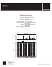
Figure 3. 12V Trigger Figure 4. Power Mode
Figu
re 6. RCA Inputs
9
10&7
-
IN
OUT
12V Trigger
+
Trigger Normal
Auto On
IN
L
L
R
L
R
R
Speaker IN
IN OUT
Line 1 Line 2
Line 1 Line 2
+ +
- -
V
V
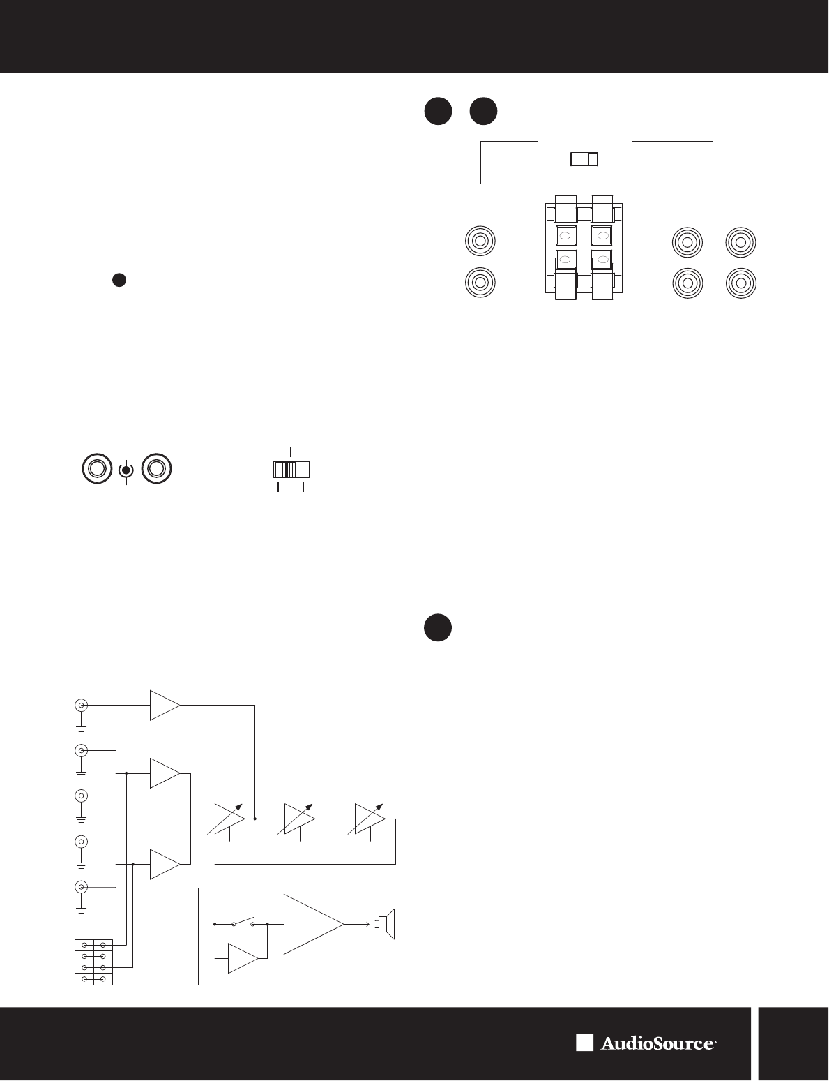
Figure 5. LFE Block Diagram
LFE Input
Left Input
Left Output
Right Input
Right Output
High Level
Input
Gain
18dB Variable
Subsonic Filter
(5-50Hz)
18dB Variable
Crossover
(40-500Hz)
Selectable
Soft Limiter
Power Amplifier
To Speaker
The built in delay of 4 seconds will automatically, in most instances,
accommodate the nature of the source connected to the “Line 1 IN”
RCAs. As an example, if the “Line 1 IN” source was a CD Changer, the
delay should be enough to prevent switching back to the “Line 2 IN”
source while the changer moves from one disc to another.