


Power
AMPSUB210
OWNER’S MANUAL
9200 North Decatur St. Portland, OR 97203 • 503.286.9300 • www.audiosource.net
4
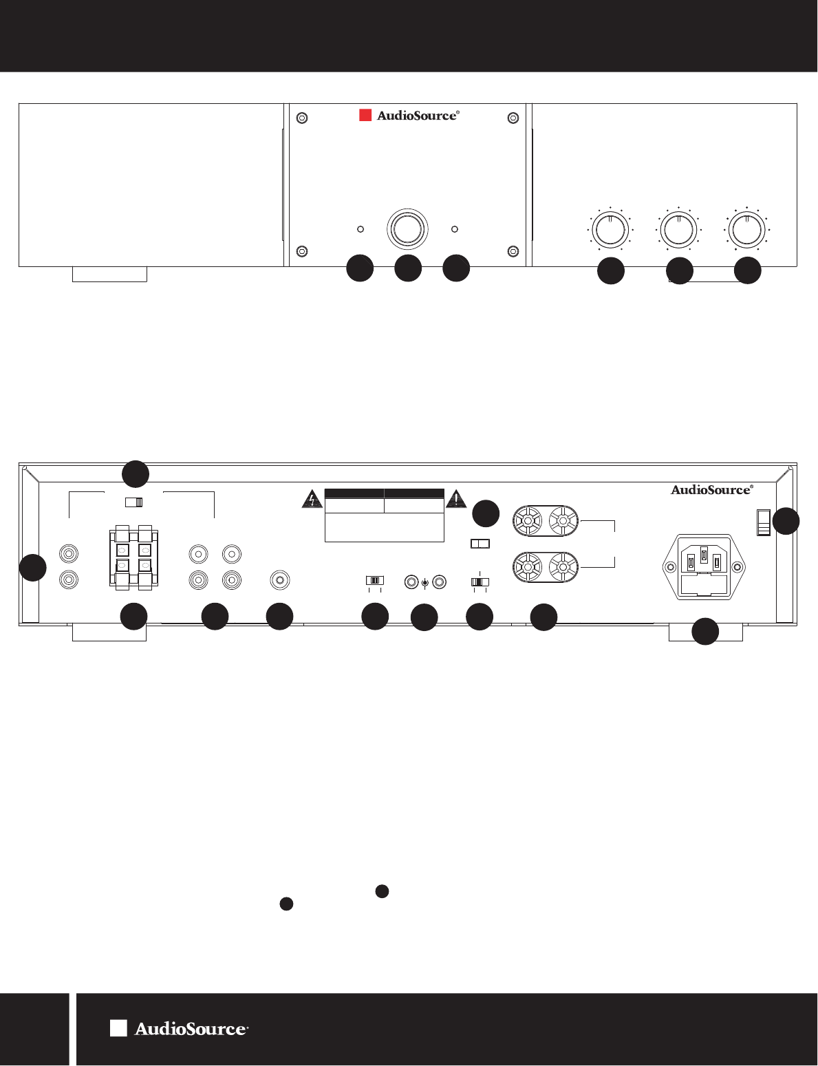
1. Power
The front panel power switch switches the AMPSUB210 on or off. Red
LEDs behind the faceplate indicate power status. Whenever the amplifier’s
power switch is in the “ON” position the ring around the button is illuminated.
When the amp is “Active” (receiving signal) the side lenses become
illuminated and the signal LED shows green. During “Standby” status (no
signal) the side lenses are not illuminated and the signal LED shows orange.
2. Signal LED
4. Subsonic Filter
Set between 5Hz and 50Hz to filter out unwanted lower frequencies.
5. Variable Crossover
Sets crossover frequency between 40Hz and 500Hz.
FRONT PANEL CONTROLS
7. Line 1 Input
A switching input that can be used if a second source is desired and will
take over when a signal is present and has at least a 5mV level. Whenever
there is no signal at this input, or a signal with less than 5mV level, the
amplifier switches back to the Line 2 or “primary” input.
8. Speaker Level Input Line Select
Switches the input of the speaker level input to Line 1 or Line 2.
9. Speaker Level Input
Can be used to connect a source with speaker level output instead of line
level outputs. Use the Speaker Level Input Line Select to route the source
to Line 1 or Line 2.
10. Line 2 Input/Output
The primary line level input and output for a single source connection.
11. LFE Input
Optional connection to LFE output from your receiver. Bypasses amplifier
volume control, use receiver to set levels. Also set Variable Crossover to
full clockwise position (500Hz) and Subsonic Filter slightly lower than your
woofer’s F3 point, or between 9 and 12 o’clock if woofer specs unavailable.
See block diagram (figure 5) on page 5.
12. Soft Limiter Switch
When “ON” reduces extreme signal peaks which may damage your speakers
and cause audible distortion.
13. 12V Trigger
Allows the AMPSUB210 to be powered on by other electronics or to power
on other electronics via a 3.5mm mini phone plug cable.
14. Power Mode
Sets the power on option of the AMPSUB210. Set it to Normal for manual
power on/off. Set to Auto-On for signal sensing. Set to Trigger if the 12V
Trigger input is used.
15.
16. Speaker Output
Dual internally bridged speaker output terminals. If connecting two speakers
they must be minimum 8 ohms each. DO NOT BRIDGE.
17. Mains Power Inlet & Fuse Holder
Accepts IEC type line cord. A fuse in the integrated holder provides safety
protection from fault conditions: replace fuse with one of same type
and rating only.
18. Mains Voltage Selector
Voltage selection switch is preset to 115V (USA). For use in areas which
require 230V contact your dealer. Fuse must be of type and rating marked
on amplifier for use at local mains voltage.
REAR PANEL CONTROLS
6
4
1
7
8
9 10 11
12
13
14
Figure 1. Front Panel
Figu
re 2. Rear Panel
2 3
3. Clip LED
Blinks red during signal clipping or protect. For clipping: reduce volume
slightly. For protect: check speaker wires for shorts or extreme low
impedance (< 4 ohms).
Light Bar Display Control
Turns light bar display on front panel on or off. Does not control Signal/Clip
LEDs or power button light ring.
Signal Clip
AMPSUB210
Subwoofer Power Amplifier
Min
Max
Volume
Min
Max
Volume
40Hz
500Hz
Variable
5Hz
50Hz
Subsonic
5
6. Volume Control
Adjusts amplifier volume.
-
IN
L
L
R
L
R
R
Speaker IN
IN OUT
Line 1 Line 2
Line 1 Line 2
+ +
- -
V
V
Serial Number:
IN
OUT
12V Trigger
+
Trigger Normal
Auto On
115V~ 60Hz 700W
FUSE:T6.3AL 250V
FUSE:T3.15AL 250V
230V~ 50Hz 700W
MODEL AMPSUB210
Custom Manufactured in China
CAUTION: See User Manual Before
Replacing Fuse
-
+
-
+
Use Class 2 Wiring
Minimum Impedance:
4 ohms Combined Load
AVIS: RISQUE DE CHOC ELECTRIQE
NE PAS OUVRIR CE CARTER
RESERVE AU PERSONNEL AUTORISE
RISK OF FIRE OR ELECTRIC SHOCK
DO NOT OPEN
CAUTION: TO PREVENT ELECTRICAL SHOCK DO NOT REMOVE
COVER. NO USER SERVICEABLE PARTS INSIDE. REFER SERVICING TO
QUALIFIED PERSONNEL.
WARNING: TO PREVENT ELECTRICAL SHOCK DO NOT REMOVE
COVER. NO USER SERVICEABLE PARTS INSIDE. REFER SERVICING TO
QUALIFIED PERSONNEL.
CAUTION AVIS
LFE
IN
Limiter
ON OFF
On Off
Light Bar Display
15
16
17
18
4
5