


Specifications are subject to change without notice
AtlasSound.com
1601 JACK MCKAY BOULEVARD ENNIS, TEXAS 75119 U.S.A. • TELEPHONE: (800) 876-3333 • FAX: (800) 765-3435
©2008 ATLAS SOUND LP Printed in U.S.A. ATS002102 RevD 2/08 PP
OWNER'S MANUAL
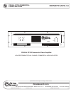
CP400 & CP700 COMMERCIAL
POWER AMPLIFIER
6
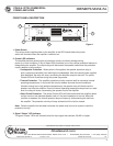
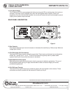
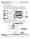
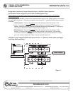
9. Stereo/Parallel/Bridge Switch
This 3 position switch changes the operating mode of the amplier. DO NOT move this switch when
the amplier is powered up and connected to a load.
• Stereo - When the switch is set to this position, the amplier operates as two independent
ampliers. Use this position for stereo program material or for two discreet paging/sound
masking zones.
• Parallel - When the switch is set to this position a single mono input signal is to be used.
Connect the input wiring to either channel 1 OR channel 2. The one input signal will drive both
amp channels. Use this position when two speaker zones are being fed by a mono signal.
(See note below)
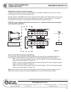
• Bridge - When the switch is set to this position, connect the mono input signal to channel 1
ONLY. The speaker load is connected across the two positive terminals as shown in Figure 7 on
page 10. The amplier will deliver approximately twice the voltage across the load. Please
observe the minimum load specication when operating in Bridge mode.
Note: A 6 dB loss of output power will occur when operating in parallel mode. To over come this loss,
connect the positive terminal on input 1 to the positive terminal on input 2 and connect the negative
terminal on input 1 to the negative terminal on input 2. Short lengths of 22-gauge wire can be used.
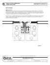
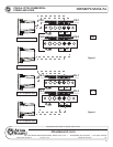
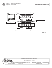
10. CH1/CH2, Low Impedance Speaker Outputs
The amplier direct speaker outputs bypass the internal constant voltage transformers and are used
for direct connection to loudspeakers. The amplier will operate into 2, 4, and 8 Ω loads. The use
of appropriately sized spade lugs is recommended for speaker wire termination; connect the speaker
line common to the “-” terminal and the positive lead to the “+” terminal.
For high power applications, use the proper gauge wire for the speaker connections. Contact
Atlas Sound Tech Support (1-800-876-3333) for assistance in determining the proper size wire.
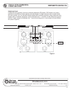
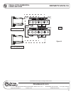
11. CH1/CH2, 25/70.7/100V Speaker Outputs
The amplier will drive constant voltage speaker loads for use in commercial business music/paging
systems and sound masking systems. The use of spade lugs for terminating and connecting the
speaker home runs is recommended. The speaker line common connects to the “0” terminal and
the positive lead connects to the desired voltage for required system requires for proper operation
(Figures 8,9,10; Pages 11-12).
Calculating Constant Voltage Loads
To calculate the maximum quantity of transformer coupled loudspeakers you can safely connect
to the amplier, rst add up the total number of speakers that will be connected to one channel
of the amplier, then multiply that total speaker number by the tap setting you plan to use. The
result will be the load in watts that the amp output channel will see. It is good engineering practice
to leave a 20% margin below the maximum rated output power of the amplier. In this case, one
channel of the amplier can supply 350 W of power at 70.7V. Derate this by 20%, leaving 280 W
of power available for constant voltage speakers.