


Specifications are subject to change without notice
AtlasSound.com
1601 JACK MCKAY BOULEVARD ENNIS, TEXAS 75119 U.S.A. • TELEPHONE: (800) 876-3333 • FAX: (800) 765-3435
©2008 ATLAS SOUND LP Printed in U.S.A. ATS002102 RevD 2/08 PP
OWNER'S MANUAL
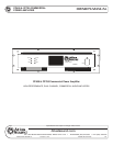
CP400 & CP700 COMMERCIAL
POWER AMPLIFIER
4
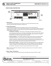
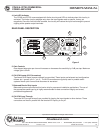
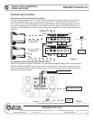
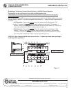
FRONT PANEL DESCRIPTION
Figure 1
1. Power Switch
This rocker switch supplies power to the amplier. A red LED located above the power
switch will illuminate when the amplier is switched on.
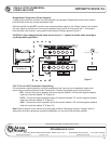
2. Protect LED Indicators
The amplier features several types of protection circuitry to prevent damage during
power-up or fault conditions. If any of these LEDs illuminate, one of the various protection features is
safeguarding the amplier. The output relays will disconnect the speaker loads when the protection
circuitry detects a fault condition.
• Loudspeaker Protection
- When power is rst applied, the speaker protection relay is
open, preventing transients from reaching the loudspeakers. After the internal power supplies
have stabilized, the relay will close, connecting the amplier output to the load. The yellow
Protect LEDs will illuminate during this power-up process.
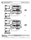
• Thermal Protection - The amplier protection circuitry monitors itself for excessive internal
operating temperatures. In the event this circuitry detects abnormal thermal conditions
(blocked cooling fan or high ambient temperatures), the speaker relay will disconnect the
speaker load from the amplier. Once the internal operating temperature drops back to a safe
level, the relay will close, reconnecting the speaker load to the amplier.
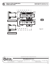
• Short Circuit Protection - The yellow Protect LEDs will illuminate should the amplier detect
a short circuit on the attached speaker load or if the load impedance is too low. When this
condition is detected, the internal speaker relays will open up, disconnecting the load from
the amplier. The protection circuitry will stay activated until the fault is cleared.
Note: Once the specic fault has been corrected, the power may have to be cycled to reset the
protection circuitry.
3. Signal “Status” LED Indicator
The green “Status” LEDs will illuminate once the input signal has reached -26 dBV or higher.
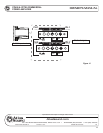
++--GND
CH-2 CH-1
AMPLIFIER INPUTS
THRU
IN
THRU
IN
CAUTION
AC100V-50/60Hz
AC120V-50/60Hz
AC230V-50/60Hz
AC240V-50/60Hz
TO REDUCE THE RISK OF ELECTRIC SHOCK
DO NOT REMOVE COVER (OR BACK)
NO USER SERV ICEABLE PART S INSIDE
REFER SERVICING TO QUALIFIED SERVICE PERSONNEL
POWER
CP700
Commercial
Power
Amplifier
Per Channel
Output Power
400 W / 4 Ohms
350 W / 70.7 V
PROTECT
LIMIT
SIGNAL
CH-1
PROTECT
POWER
LIMIT
SIGNAL
CH-2
CP700
Commercial Power Amplifier
LEVEL
-
0
0
5
6
4
0
3
2
2
6
2
2
1
8
1
6
1
4
1
2
1
0
8
6
4
2
0
LEVEL
-
0
0
5
6
4
0
3
2
2
6
2
2
1
8
1
6
1
4
1
2
1
0
8
6
4
2
0
1601 Jack McKay Blvd., Ennis, TX 75119
(800) 876-3333 AtlasSound.com
STEREO
PARALLELBRIDGE
GND
CH-1 CH-1
- 100V +
-+
70V
-+
25V
8, 4, and 2 Ohms
AUDIO TRANSFORMER
DIR. OUTPUT ISOL. OUTPUT
-+70 1000
BRIDGE
MONO
+
CH-2 CH-2
- 100V +
-+
70V
-+
25V
8, 4, and 2 Ohms
AUDIO TRANSFORMER
DIR. OUTPUT ISOL. OUTPUT
-+70 1000
BRIDGE
MONO
-
AVIS RISQUE DE CHOC ELECTRIQUE
NE PAS OUVRIR
CAUTION
RISK OF ELECTRIC SHOCK
DO NOT OPEN
M A D E IN C H I N A
2
3
4
1