


Specifications are subject to change without notice
AtlasSound.com
1601 JACK MCKAY BOULEVARD ENNIS, TEXAS 75119 U.S.A. • TELEPHONE: (800) 876-3333 • FAX: (800) 765-3435
©2006 ATLAS SOUND LP Printed in U.S.A. 00106 ATS002179 RevA 01/06 PP
OWNER'S MANUAL
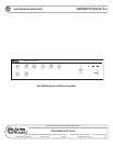
AA120M MIXER AMPLIFIER
8
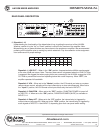
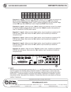
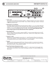
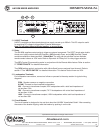
Dipswitch 5 - Input 6 - When set to the "Mix Bus" position, INPUT 6 signals are routed to the
Mix Bus and are POST Input Gain, POST Zone 2 and 3 Outputs and PRE Tone Controls.
When set to the "Amp Direct" position, INPUT 6 signals go directly to the fi nal amplifi er stage,
and are PRE Input Gain, PRE Zone 2 and 3 Outputs and POST Tone Controls.
Dipswitch 6 - Input 5 - When set to the "100mV" position, the sensitivity of Input 5 is suitable
for inputting Telephone Paging Signals. When set to the "300mV" position, the sensitivity of
Input 5 is suitable for CD/DVD player outputs.
Dipswitch 7 - Input 4 - When set to the "Line" position, Input 4 sensitivity is suitable for CD/
DVD line level outputs. When set to the "Mic" position, Input 4 sensitivity is suitable for
microphone input.
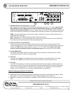
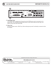
Dipswitch 8 - Input 3 - When set to the "Line" position, Input 3 sensitivity is suitable for CD/
DVD line level outputs. When set to the "Mic" position, Input 3 sensitivity is suitable for
microphone input.
Dipswitch 9 - Input 2 - When set to the "Line" position, Input 2 sensitivity is suitable for CD/
DVD line level outputs. When set to the "Mic" position, Input 2 sensitivity is suitable for
microphone input.
Dipswitch 10 - Input 1 - When set to the "Tel/Line" position, Input 1 sensitivity is suitable for
CD/DVD line level outputs. When set to the "Mic" position, Input 1 sensitivity is suitable for
microphone input.
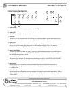
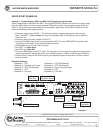
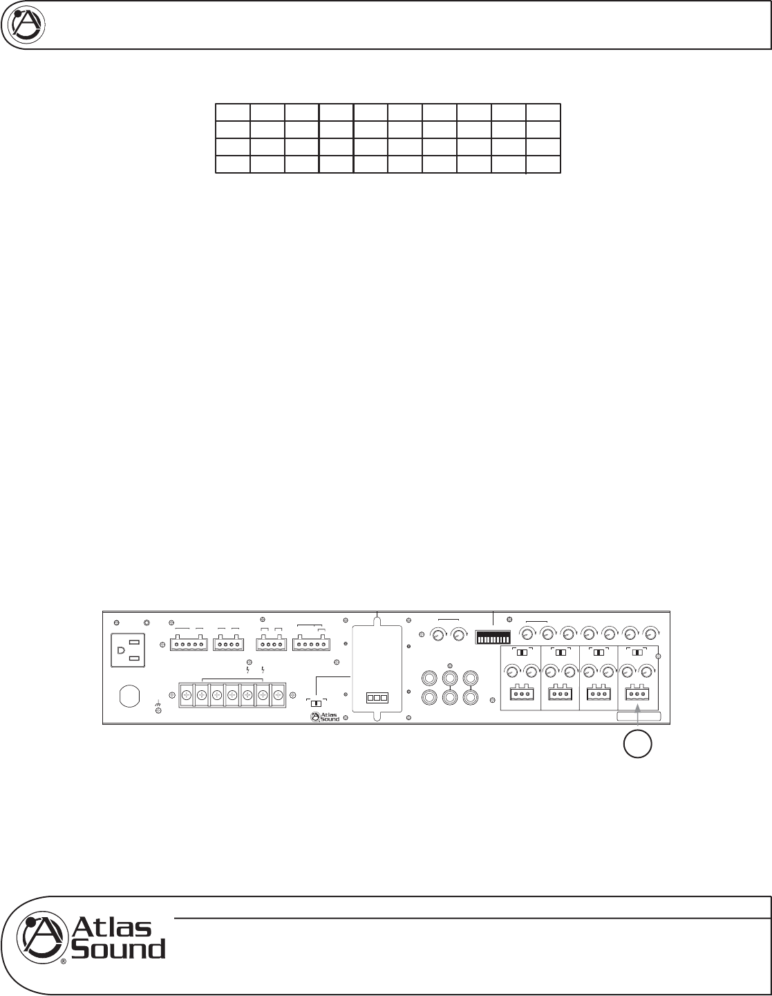
10. Input 1
Balanced mic or line level signals connect to the (+), (—), and (G) terminals. Refer to the chart at the
top of the page for the following setting. Dipswitch number 10, labeled Input 1 must be set to the
proper position for mic or line level. If you are connecting an unbalanced line level input, tie (short)
the (G) and (—) terminals together. An optional Input Isolation Transformer is available if a ground
loop problem exists. See page 23 for installation. Contact Atlas Sound for more details on the Input
Isolation Transformer.
Vox M uteVox M ute
Input 5
Level
Zone 3
Level
Zone 2
10
0
10
0
10
0
10
0
10
0
10
0
10
0
G
–
+G
–
+G
–
+G
–
+
Unswitched Outlet
120V AC 60Hz
Max 500W
Outlet Breaker
125V AC 4A
Push Reset
120V AC 60Hz 300W
100V70V25V
¡
8Com
24V DC 200mA
Relay
+
–
NC
C
NO
–
+
+–
Zone 2 Out
1W 8
Zone 3 Out
¡ ¡
600
Remote Mute VCA
+
–
G
Sel
Bridge
In/Out
Input 6
Level
Zone 3
Level
Zone 2
100100
Sens
Input 4
Trim
Input 3
Trim
Input 2
Trim
Input 1
Trim
Mute
10010
0
10
0
10
0
100100100
Send
Off
Rcv
Send
Rcv
Off
Send
Off
Rcv
Send
Off
10
0
Zone 2 Level
Zone 3 Level
Input 3 Input 2 Input 1
Pwr In
Tape Out
12345678910
R
Line Out
L
Input 5
Pre Out
Input 6
Input 4
Zone 2 Level
Zone 3 Level
Zone 2 Level
Zone 3 Level
Zone 2 Level
Zone 3 Level
£Èä£Ê>VÊV>ÞÊÛ`°]ÊÃ]Ê/8ÊÇx££Ê
nää®ÊnÇÈÎÎÎÎÊÌ>Ã-Õ`°V
77'(&C 7jbWiIekdZ77I[h_[iC_n[h7cfb_\_[h
Speaker Output 120W
Vox M ute
VoxMute
Send
Off
Rcv
CLASS 2 WIRING
Vox Mute
Chime Module
On
Mic
Mic
Mic
Mic
300mV
Amp Dir
Vox
Input 5
On
Relay
Act
Low Cut
Input 3
Input 4Input 5
Input 6
Phantom
Input 1
Input 2
1
9
87
6
5342
10
VCA
Off
Line
Line
Line
Tel/Line
100mV
Mix Bus
CCMaster
Off
10