


Specifications are subject to change without notice
AtlasSound.com
1601 JACK MCKAY BOULEVARD ENNIS, TEXAS 75119 U.S.A. • TELEPHONE: (800) 876-3333 • FAX: (800) 765-3435
©2006 ATLAS SOUND LP Printed in U.S.A. 00106 ATS002179 RevA 01/06 PP
OWNER'S MANUAL
AA120M MIXER AMPLIFIER
23
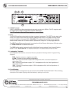
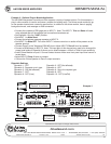
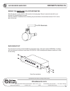
INTERNAL JUMPER LOCATIONS
Remove the power cord from the wall before proceeding as hazardous voltages are present inside
the AA120M.
1. Disconnect the power cord from the wall socket.
2. Remove the screws securing the top cover of the AA120M, and remove the cover.
3. Refer to circuit board layout in the diagram below to locate the jumpers.
4. Configure the jumpers to suit your application.
5. Replace top cover and secure using the screws removed in step 2.
6. Re-install the power cord and test the configuration.
If you have questions or need assistance with your specific application, contact Atlas Sound Tech Support
at 1-800-876-3333.
WARNING
ZONE 2
ZONE 3
MUTE CC
INPUT 2
INPUT 3INPUT 4
INPUT 5
INPUT 6
MAIN PCB
RCV VOX MUTE
R524
C626
R623
C623
AB
J517
Q547
Q546
BA
J505
AB
J502
BA
J506
1
CN504
1
CN506
1
CN503
D517
C633
C664
C665
AB
J508
BA
J511
AB
J510
BA
J514
AB
J515
BA
J509
AB
J512
BA
J513
BA
J504
AB
J503
BA
J507
AB
J516
C597
C646
C669
D505
D507
D520
D523
D532
Q50
Q543
Q550
R516
R529
R585
R586
R588
R
620
6
21
R624
R640
R641
R668
R689
R
690
R699
C565
C560
C573
C572
C570
C544
C668
C576
C574
C628
C522
C545
C566
R548
R622
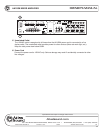
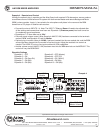
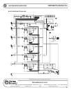
INPUT2~6 TO ZONE 2
A-PRE MUTE
B-POST MUTE
INPUT2~6
CC MUTE RECEIVE
A-ON B-OFF
INPUT5
VOX MUTE RECEIVE
A-ON B-OFF
INPUT2~6 TO ZONE 3
A-PRE MUTE
B-POST MUTE
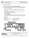
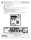
Jumper locations on MAIN PCB
Transformer
Optional Input
D535
IT501
JP502
JP501
D522
R561
R562
C535
C534
4
C625
R676
R661
R618
R610
R539
C589
R609
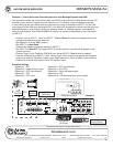
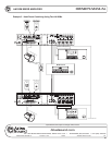
TRANSFORMER
OPTIONAL INPUT
X'FMR BYPASS
X'FMR IN
JUMPERS
XFMR location on MAIN PCB