


Specifications are subject to change without notice
AtlasSound.com
1601 JACK MCKAY BOULEVARD ENNIS, TEXAS 75119 U.S.A. • TELEPHONE: (800) 876-3333 • FAX: (800) 765-3435
©2006 ATLAS SOUND LP Printed in U.S.A. 00106 ATS002179 RevA 01/06 PP
OWNER'S MANUAL
AA120M MIXER AMPLIFIER
10
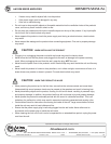
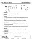
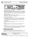
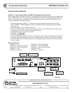
17. VOX Mute Switch For Channels 2, 3, 4, and 6
Each 3-position switch sets the VOX mute status individually for Inputs 2, 3, 4, and 6. Note: All VOX
Mute settings are over ridden when the internal Remote Mute jumpers are installed and the
contacts are connected together. Input 5 is shipped with an internal VOX Mute jumper installed and
will be muted when any channel is set to Mute Send and signal is present at the corresponding input.
SEND - Sends a (VOX) Mute command when audio is present at the input to other channels set to
(VOX) Mute RCV (Receive).
OFF - Bypasses the (VOX) Mute Send and RCV (Receive) functions.
RCV (VOX Receive) - Inputs will be Muted when other Input Channels are set to to the (VOX) Mute
Send position and audio is present at the corresponding input.
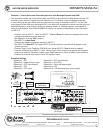
18. Zone 2 And Zone 3 Level Controls
These rotary controls will vary the signal level at the Zone 2 and Zone 3 output terminals. Fully
counter-clockwise (0) is off, fully clockwise (10) is the maximum output level. Both Zone 2 and 3 level
controls are PRE channel level controls for Inputs 1, 2, 3, 4, 5, and 6. Note: Zone 2 and 3 level
controls function identically to their corresponding inputs. See number 28 for more details.
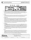
19. Input 6 Module Slot
The Module Slot accepts optional industry standard input modules from Atlas and other vendors.
Contact Atlas Sound for a full list of module types.
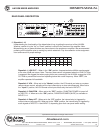
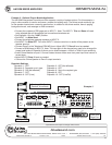
20. Tape Out
Line level mono signals are available at this jack for connection to recording devices. The signal
available here is PRE tone control and low cut filter and comes from the internal mix bus.
21. Line Out
The LINE OUT connector is useful for providing unbalanced line level signal to another amplifier or
other external devices. Prior to using this feature one must understand where the internal signal pick
up point is so you can decide if it is correct for your application. We suggest you refer to the block
diagram of the AA120M to have a complete understanding of the signal flow.
Note the following conditions for LINE OUT
A. Pre Low Cut Filter
B. Post Tone Controls (meaning the settings for the Bass and Treble controls affect this signals output).
Note: Refer to "Low Cut Filter Switch for complete understanding of the LCF feature."
C. Post Amp In (meaning any signal that is inserted into the Pre AMP In jack will be present at the Line
Out).
Vox M uteVox M ute
Input 5
Level
Zone 3
Level
Zone 2
10
0
10
0
10
0
10
0
10
0
10
0
10
0
G–+G–+G–+ G–+
Unswitched Outlet
120V AC 60Hz
Max 500W
Outlet Breaker
125V AC 4A
Push Reset
120V AC 60Hz 300W
100V70V25V
¡
8Com
24V DC 200mA
Relay
+
–
NC
C
NO
–+ +–
Zone 2 Out
1W 8
Zone 3 Out
¡ ¡
600
Remote Mute VCA
+–
G
Sel
Bridge
In/Out
Input 6
Level
Zone 3
Level
Zone 2
100100
Sens
Input 4
Trim
Input 3
Trim
Input 2
Trim
Input 1
Trim
Mute
10010
0
10
0
10
0
100100100
Send
Off
Rcv
Send
Rcv
Off
Send
Off
Rcv
Send
Off
10
0
Zone 2 Level
Zone 3 Level
Input 3 Input 2 Input 1
Pwr In
Tape Out
12345678910
R
Line Out
L
Input 5
Pre Out
Input 6
Input 4
Zone 2 Level
Zone 3 Level
Zone 2 Level
Zone 3 Level
Zone 2 Level
Zone 3 Level
£Èä£Ê>VÊV>ÞÊÛ`°]ÊÃ]Ê/8ÊÇx££Ê
nää®ÊnÇÈÎÎÎÎÊÌ>Ã-Õ`°V
77'(&C 7jbWiIekdZ77I[h_[iC_n[h7cfb_\_[h
Speaker Output 120W
Vox M ute
VoxMute
Send
Off
Rcv
CLASS 2 WIRING
Vox M ute
Chime Module
17
19 2021 18