


Specifications are subject to change without notice
AtlasSound.com
1601 JACK MCKAY BOULEVARD ENNIS, TEXAS 75119 U.S.A. • TELEPHONE: (800) 876-3333 • FAX: (800) 765-3435
©2006 ATLAS SOUND LP Printed in U.S.A. 00106 ATS002179 RevA 01/06 PP
OWNER'S MANUAL
AA120M MIXER AMPLIFIER
11
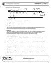
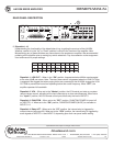
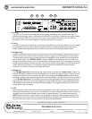
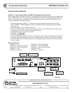
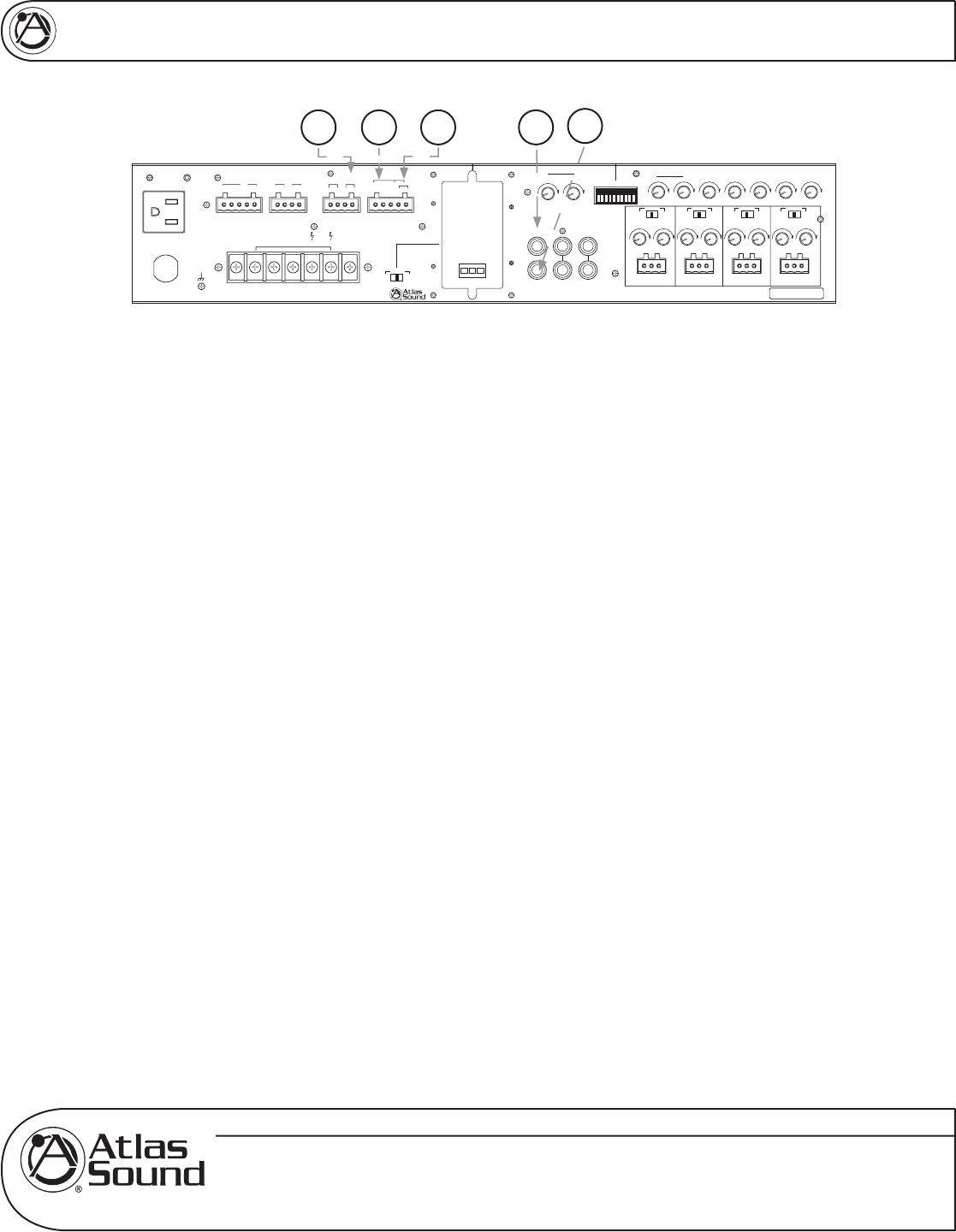
22. Pre Out
The PRE OUT connector has Post tone control signals available to drive another power amp or
external audio devices. Use in conjunction with the AMP IN connector, an effects loop can be created
by connecting the PRE OUT jack to a device such as an equalizer then back out to the AMP IN
connector. See the connection diagram in the setup section of this manual.
23. Pwr In
The AMP IN connector is useful for converting the AA120M into a slave amp. When a line level signal
is connected to this input, the internal connection between the preamp and internal power amp is
broken. Audio signals applied to this connector are post tone control and pre master control.
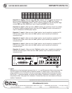
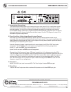
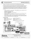
24. Bridge In/Out
Certain installations have the need to combine one or more mixers together. These mixers may be in
different rooms of an install but have the need to share a page or music throughout the installation.
These terminals provide a way to send and receive balanced line level signals from the internal mix
bus of the AA120M. The "BRIDGE IN/OUT" feature is PRE Tone Controls and Low Cut Filter. The
Bridge In/Out feature allows you to send and receive a balanced signal. This is important for allowing
longer distances between the mixers. Note: This function should only be done with other Atlas Sound
mixers that have this feature. The Send and Receive signals are combined through the same
terminals. To activate this feature see Bridge Sel below.
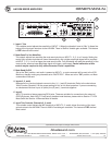
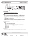
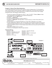
25. Bridge Sel
The "Bridge Select (Sel)" terminals are the access point to activate the "Bridge In/Out" feature. To
activate the feature connect the two points together via an external contact closure. These two points
must be connected to send or receive any signal. By connecting the Bridge In/Out terminals of two
AA120M, a simple room combining system can be accomplished. If using a remote switch and closing
it, the "Bridge Select (Sel)" will combine the amps as one, opening the switch will separate the two
amps. Note: If combining 3 or 4 mixers together the output level will have to be adjusted before and
after Bridge Sel terminals are connected (shorted) together. We suggest utilizing the Remote Level
control when using this feature.
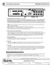
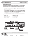
26. VCA
Remote location of the level control can be accomplished via the VCA control port. You can control
the overall level (Master) or just Input 5. This selection is made via Dipswitch position #2. Connect the
two leads from the optional remote volume control to these terminals. This remote level control is
POST Master and Input 5 Level Controls. Set the system's maximum levels using the amplifier level
controls and then use the remote VCA potentiometer as an attenuator from the maximum levels set.
See the VCA setup section for instructions on wiring up the potentiometer.
Vox M uteVox Mute
Input 5
Level
Zone 3
Level
Zone 2
10
0
10
0
10
0
10
0
10
0
10
0
10
0
G–+G–+G–+ G–+
Unswitched Outlet
120V AC 60Hz
Max 500W
Outlet Breaker
125V AC 4A
Push Reset
120V AC 60Hz 300W
100V70V25V
¡
8Com
24V DC 200mA
Relay
+
–
NC
C
NO
–+ +–
Zone 2 Out
1W 8
Zone 3 Out
¡ ¡
600
Remote Mute VCA
+–
G
Sel
Bridge
In/Out
Input 6
Level
Zone 3
Level
Zone 2
100100
Sens
Input 4
Trim
Input 3
Trim
Input 2
Trim
Input 1
Trim
Mute
10010
0
10
0
10
0
100100100
Send
Off
Rcv
Send
Rcv
Off
Send
Off
Rcv
Send
Off
10
0
Zone 2 Level
Zone 3 Level
Input 3 Input 2 Input 1
Pwr In
Tape Out
12345678910
R
Line Out
L
Input 5
Pre Out
Input 6
Input 4
Zone 2 Level
Zone 3 Level
Zone 2 Level
Zone 3 Level
Zone 2 Level
Zone 3 Level
£Èä£Ê>VÊV>ÞÊÛ`°]ÊÃ]Ê/8ÊÇx££Ê
nää®ÊnÇÈÎÎÎÎÊÌ>Ã-Õ`°V
77'(&C 7jbWiIekdZ77I[h_[iC_n[h7cfb_\_[h
Speaker Output 120W
Vox M ute
VoxMute
Send
Off
Rcv
CLASS 2 WIRING
Vox Mute
Chime Module
22
2324 2526