


Page 11
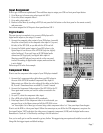
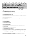
Digital Audio Connections
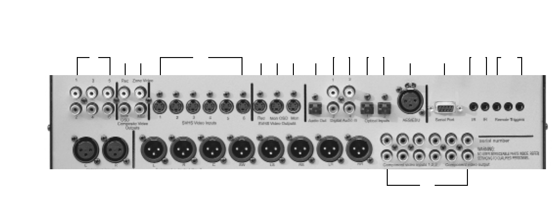
(17) COAXIAL DIGITAL AUDIO INPUTS 1 THROUGH 4
Connect the coaxial digital output cables from your source devices to these inputs. You can freely associate the digital
inputs to any source (see menu option for further reference).
(18) OPTICAL DIGITAL AUDIO INPUTS 1 & 2
These connections require optical cables and connectors. You can freely associate the optical inputs to any audio source
(see menu option for further reference).
(16) OPTICAL DIGITAL AUDIO OUTPUT
Connect the optical input of your digital recorder to the DIGITAL output. The selected primary digital source is fed to
this output in optical format.
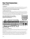
Other Connections
(19) BALANCED AUDIO INPUT
This connection requires an XLR cable and
connectors Pin 2 is “hot.”
(20) RS 232 CONTROL INTERFACE
Via this interface, you can connect the ATP 8500 to a home automation system. Contact your dealer for details.
(21) IR INPUT/OUTPUT
These connections are for an additional InfraRed remote controller.
(22) REMOTE TRIGGER OUTPUTS 1 THROUGH 3
You can connect the DC trigger inputs of any audio or other device to the TRIGGER outputs. The TRIGGER output may
be activated when the ATP 8500 is switched out of STANDBY and immediately turned off again when the ATP 8500 is
switched into STANDBY again. You can also program the TRIGGER outputs to be activated under other conditions (see
menu section). The TRIGGER outputs deliver 12 VDC at a maximum total current (for the three outputs) of 200 mA.
CAUTION: CONNECT OR DISCONNECT THE TRIGGERS ONLY WHEN THE POWER SWITCH IS OFF,
OR THE UNIT IS DISCONNECTED FROM MAINS POWER!
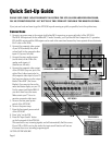
17 189 12 21 2216151310 11 14 19 20
23