


7
Operating Manual - VCM-88, VCM-88E, RD-8, RW-8 Level Controllers
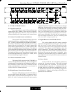
5.13 Data Protocol Selector (VCM-88E only)
These two DIP switches allow selection of four data
protocols. The Standard protocol is selected for use with
current Ashly, AMX, or Crestron controllers. The Protea
Software protocol is selected for use with Ashly's Protea
System Software. The MIDI protocol is used for control
by a MIDI device. The Legacy protocol is selected for con-
trol by a legacy Ashly or AMX device. On the VCM-88,
protocols are selected using internal jumpers. See fig. 9.2
for VCM-88 data protocol details.
5.14 MIDI (VCM-88 only)
MIDI In and MIDI Thru jacks allow complete
implementation of the VCM-88 in a MIDI network. An in-
ternal jumper selection is required to operate under MIDI
control. For specific details regarding internal selection,
as well as continuous controller numbers and values, see
section 9.5.
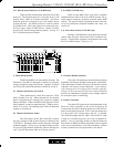
5.15 Slave Data In/Out (VCM-88E only)
Multiple VCM-88E units can be placed in the same
control loop using the Slave Data In/Out euroblock con-
nectors. Control data originates from another unit under
RS-232 or MIDI control. (See fig. 9.5)
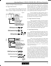
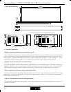
6. RD-8/RW-8 Remote
The RD-8 and RW-8 are functionally the same. The
difference is the RW-8 is designed to mount as a wall plate
using a standard 4-gang electrical box. Both the VCM-88
and VCM-88E respond identically to the RD-8 or RW-8.
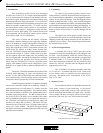
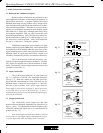
6.1 Channel and Master On Switch
These push-buttons switch the respective VCM-
88(E) channel on or off. When switched on, the channel
gain is controlled by the setting of the respective channel
fader on the RD-8. When switched off, the respective VCM-
88(E) channel is muted to approximately -75dB by the in-
ternal VCA circuit. The adjacent green LED is lit when the
channel is switched on.
6.2 Channel and Master Fader
The slide faders on the RD-8 and RW-8 control
the gain (volume) in dB of their respective channel in the
VCM-88(E). The Master fader controls the gain of all eight
channels together. That is to say, the master fader can raise
or lower all eight channels uniformly without affecting the
“mix” just like the master fader on a mixing console.
6.3 Remote Disable Indicator
This red LED illuminates when the RD-8 has been
disabled by the Remote Disable Switch on the VCM-88(E).
When the Remote Disable LED goes off, the RD-8 remote
controller will resume normal operation. Avoid dramati-
cally changing the level settings of the controller when dis-
abling it or disconnecting the data line, as the VCM-88(E)
master will immediately respond to any changes made to
the controller upon re-connecting.
6.4 Data Connection
The male XLR jacks on the side and bottom of the
RD-8 are wired in parallel so that an XLR plug may be
inserted into the side for desktop operation or into the bot-
tom for rack-mount operation. Pin 2 is the data output, pin
3 is the positive DC voltage input, and pin 1 is ground.
This XLR data output may be “split” with an XLR Y-cable
to feed two VCM-88(E) units to give stereo 8-channel ca-
pability. Also, by installing factory customized firmware
into the device ROM, the RD-8 slide faders can be assigned
to any (or several) arbitrary VCM-88(E) channels. Contact
a factory technical service representative for details.
∞
Gain (dB)
6.4 6.3
6.1
6.2